
Quality of service network and method

Inactive Publication Date: 2011-04-05
TEJAS NETWORKS
View PDF24 Cites 2 Cited by
  • Summary
  • Abstract
  • Description
  • Claims
  • Application Information

AI Technical Summary

Benefits of technology

"The present invention solves the problem of collisions in conventional networks by providing a network where all the routes through the network are defined in advance and an admission control protocol for each edge device based on global network statistics. This increases the efficiency of the network. The invention also includes an edge device with admission control and a calculator for calculating the admission control and routing scheme based on data collected from the edge device and global network statistics. The invention can be applied to any sub-network or metro network of a carrier network."

Problems solved by technology

In this topology, each node has unlimited and uncontrolled access to network resources.
However, with this kind of multiplexing, several inherent problems arise:Network behavior is erratic and unpredictable due, in part, to collisions between data packets that different nodes are attempting to transmit at the same time.Network resources are unfairly distributed, with ingress nodes which are closer to certain egress nodes getting much more bandwidth than ingress nodes which are remote from those egress nodes.Traffic parameters, such as delay (the time lag between the departure of a signal from the source and the arrival of the signal at the destination) and jitter (the variance from the average delay), cannot be assured.It is impossible to guarantee quality of service, in terms of assured bandwidth, bound delay and jitter, and packet loss, to differentiated customers or services, as defined in Service Level Agreements (SLAs).
These solutions, however, are based on local (per hop) calculations and information, and are prone to errors due to global dynamic changes, e.g., a sudden rise in network resource use in one node that causes the network to be congested for the time (typically, a few seconds) it takes for the resource management protocols to stabilize the network.
This results in under-utilization of network resources at other times.
Thus, it is limited in its efficiency as it has no knowledge of the state of the overall system.
Furthermore, there is no provision for admission control of data to the network, so collisions are likely.
This system, which is limited in use to an IP networking system, must learn the new topology state of the network whenever there is a change of any sort.
Since these computations are required continually, the network is burdened with large quantities of computations, and automatically “updates” routing tables, substantially in real time, even if there are no changes, thereby slowing down data transfer in the network as a whole.
In addition, this system has no provision for admission control of data to the network, leading to inefficient transfer of data traffic.
These networks suffer from the disadvantage that they are inefficient.
Furthermore, it will be appreciated that the complex routing protocols described above, designed for generalized global and dynamic topology networks, which require constant updating of routing tables in accordance with the actual state of the various nodes in the network, are not suitable for establishing routes in the routing domain of a carrier network, such as a metro network.
This is because they are too complex, and they are not resource efficient or cost efficient.
None of these prior art methods provides Quality of Service for data packets in metro and sub-networks of carrier networks, and so forth, which is close to optimal.
It has now been appreciated that collisions are common in conventional networks, even if using an admission control protocol, such as those described above, since there are no fixed routes for the data, on the one hand and, on the other hand, collisions are also common in conventional networks having static routing since there is no admission control taking into account the quantity of data entering the network at any given time.

Method used


Image

  • Quality of service network and method
  • Quality of service network and method
  • Quality of service network and method

Examples


Embodiment Construction

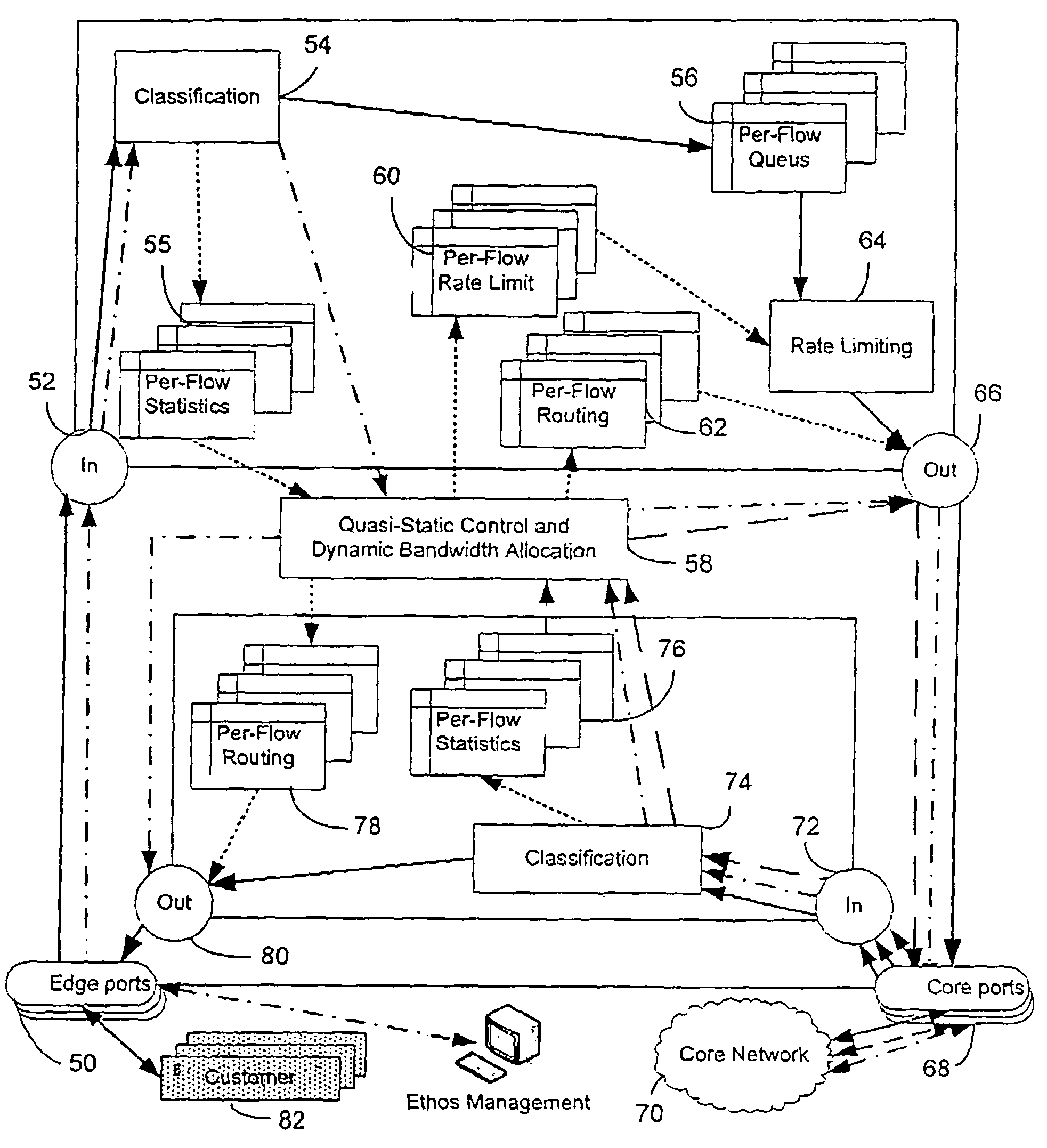
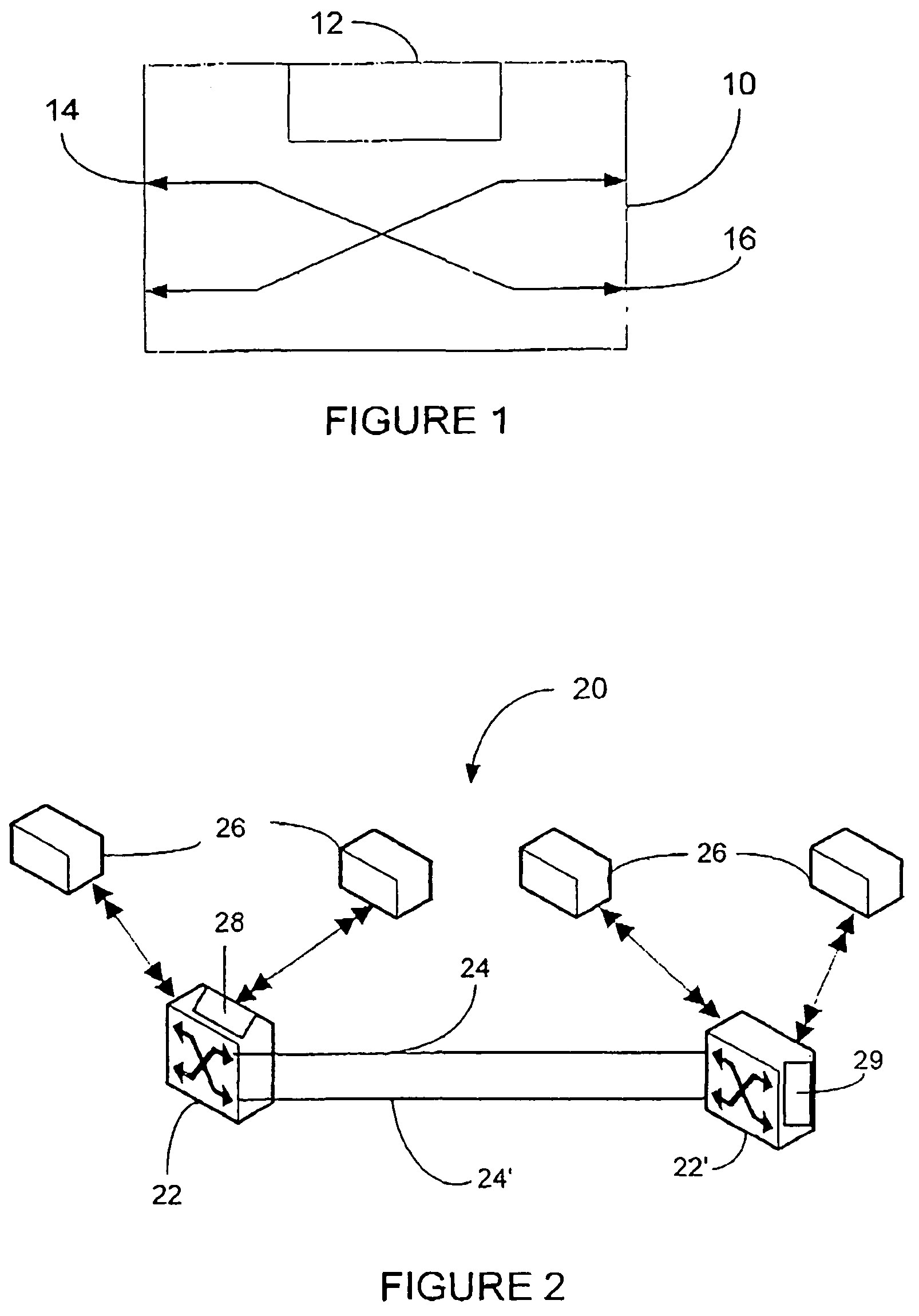
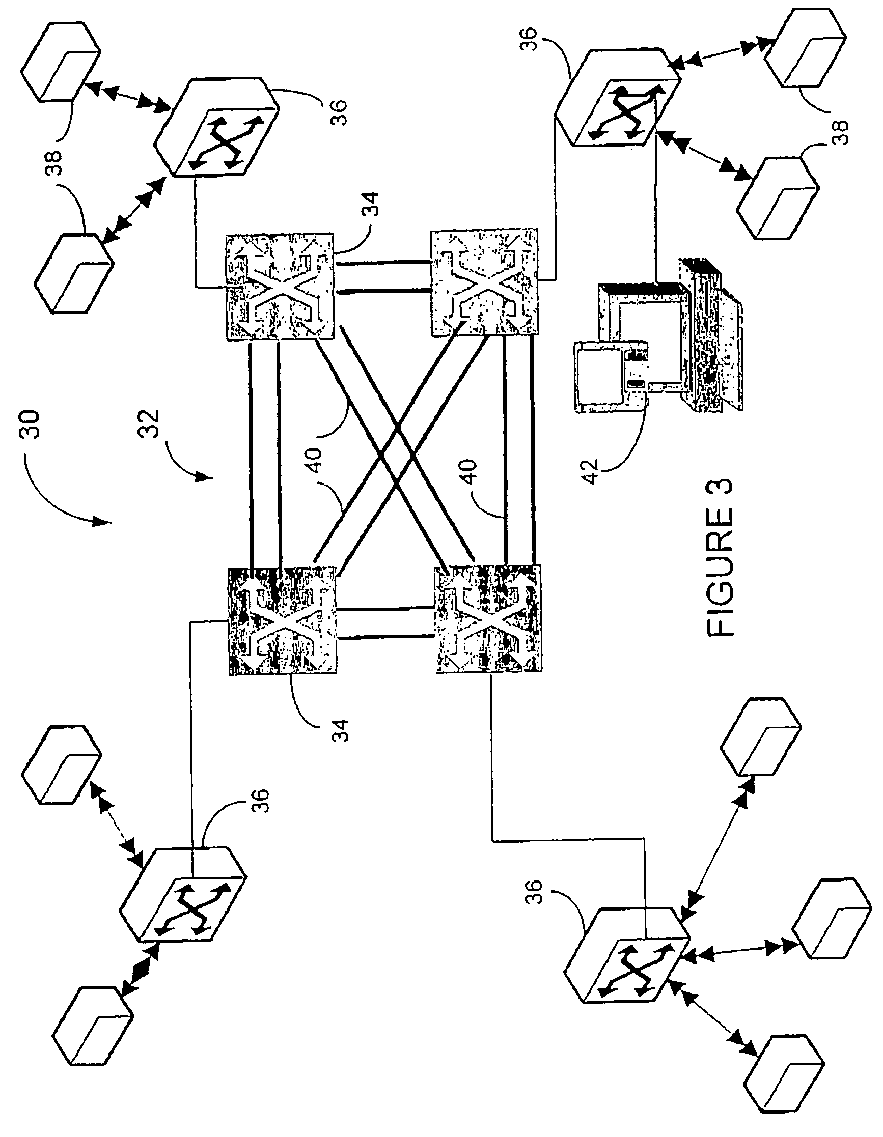
[0050]The present invention relates to an edge device for a telecommunications network and to a telecommunications carrier network, particularly an Ethernet network, which is able to provide pre-defined Quality of Service (QOS) to its various customers. This is accomplished by providing the network with a static, or substantially static, routing scheme, together with dynamic admission control for all data traffic entering the network. The network includes a plurality of configurable edge switching devices, usually coupled to a core network, which implement both admission control for data traffic entering the edge devices, and static or quasi-static routing for the traffic through the network, both based on input knowledge of all the network physical and logical links. Preferably the system utilizes admission control based on bandwidth demand statistics throughout the entire network, and quasi-static routing based on network bandwidth utilization statistics throughout the entire netw...


PUM


Abstract

A configurable edge device for use in a network, the edge device being adapted and configured to be coupled to at least one other edge device in a network, and including an admission controller for controlling admission of data traffic onto a pre-defined flow over a physical link, and a router for routing the data traffic through the edge device onto the pre-defined flow in accordance with a pre-defined routing scheme, wherein operation of the admission controller and the router is controlled in accordance with data defining all physical and logical links in the network; a telecommunications carrier network for data traffic, the network including at least two such configurable edge devices, and a method for transmitting data traffic through such an edge device.

Description

RELATED APPLICATION[0001]This application is related to Israel Patent Application Serial No. 167059 filed on Feb. 23, 2005, entitled “NETWORK EDGE DEVICE AND TELECOMMUNICATIONS NETWORK,” priority to which is claimed under 35 U.S.C. §119 and which is expressly incorporated herein by reference in its entirety.FIELD OF THE INVENTION[0002]The present invention relates to a network and method for providing pre-defined Quality of Service (QOS) for a packet or frame-switched network in general and, in particular, to a configurable edge device for a telecommunications network and method for providing QOS for data communication over carrier networks.BACKGROUND INFORMATION[0003]Packet switched networks generally are based on shared bandwidth topology. In this topology, each node has unlimited and uncontrolled access to network resources. A commonly used network access system, known as statistical multiplexing, transmits data simultaneously from any number of input devices attached to the netw...

Claims


Application Information

Patent Timeline
Patent Type & Authority Patents(United States)
IPC IPC(8): H04L12/28
CPCH04L12/5695H04L45/02H04L47/15H04L47/829H04L47/781H04L47/808H04L47/822H04L47/762H04L47/70
Inventor PORAT, HAIM
Owner TEJAS NETWORKS
Learn More