System and method for adaptive removal of delay jitter effect and low end-to-end delay

a delay jitter and adaptive removal technology, applied in the field of system and method for adaptive removal of delay jitter effect and low end-to-end delay, can solve the problems of further degradation of network quality, packet loss, and delay exceeding 300 ms, and achieve the effect of preventing the interactivity of voice communications

Active Publication Date: 2011-04-05
VERIZON PATENT & LICENSING INC
View PDF11 Cites 10 Cited by
  • Summary
  • Abstract
  • Description
  • Claims
  • Application Information

AI Technical Summary

Problems solved by technology

With VoIP, for example, an end-to-end delay less than 150 milliseconds (ms) may not be perceived by a human ear, delay between 150 and 300 ms may be perceptible but ideal, and delay exceeding 300 ms may be unacceptable and hinder the interactivity possible in voice communications.
Such a configuration may lead to packet loss and a further degradation of the network quality.
End-to-end delay of packets in a network may be caused by transmission delays and / or queuing delays in routers and / or other components of the network that process the packets.
Delay jitter in the network may be caused by the variation in delay experienced by individual packets.
The drawback to this approach is excessive end-to-end delay.
The drawback to this approach is that the effects of delay jitter may not be removed.
Accordingly, conventional systems and methods may disadvantageously degrade the quality of the application due to lost packets or extensive buffering to attempt to capture delayed packets.
Accordingly, these systems may not meet delay performance requirements and / or may experience severe degradation in the communication due to an extensive number of lost packets.
While the conventional MDV method may be used to remove the de-sequencing effect of delay jitter completely, the time for which the packets are buffered may be greater than necessary, thereby causing unnecessary delay before playback of the packets at the receiver.
The unnecessary delay may cause end-to-end delay to be greater than allowed for interactive real-time applications such as VoIP and VT.

Method used


Image

  • System and method for adaptive removal of delay jitter effect and low end-to-end delay
  • System and method for adaptive removal of delay jitter effect and low end-to-end delay
  • System and method for adaptive removal of delay jitter effect and low end-to-end delay

Examples


Embodiment Construction

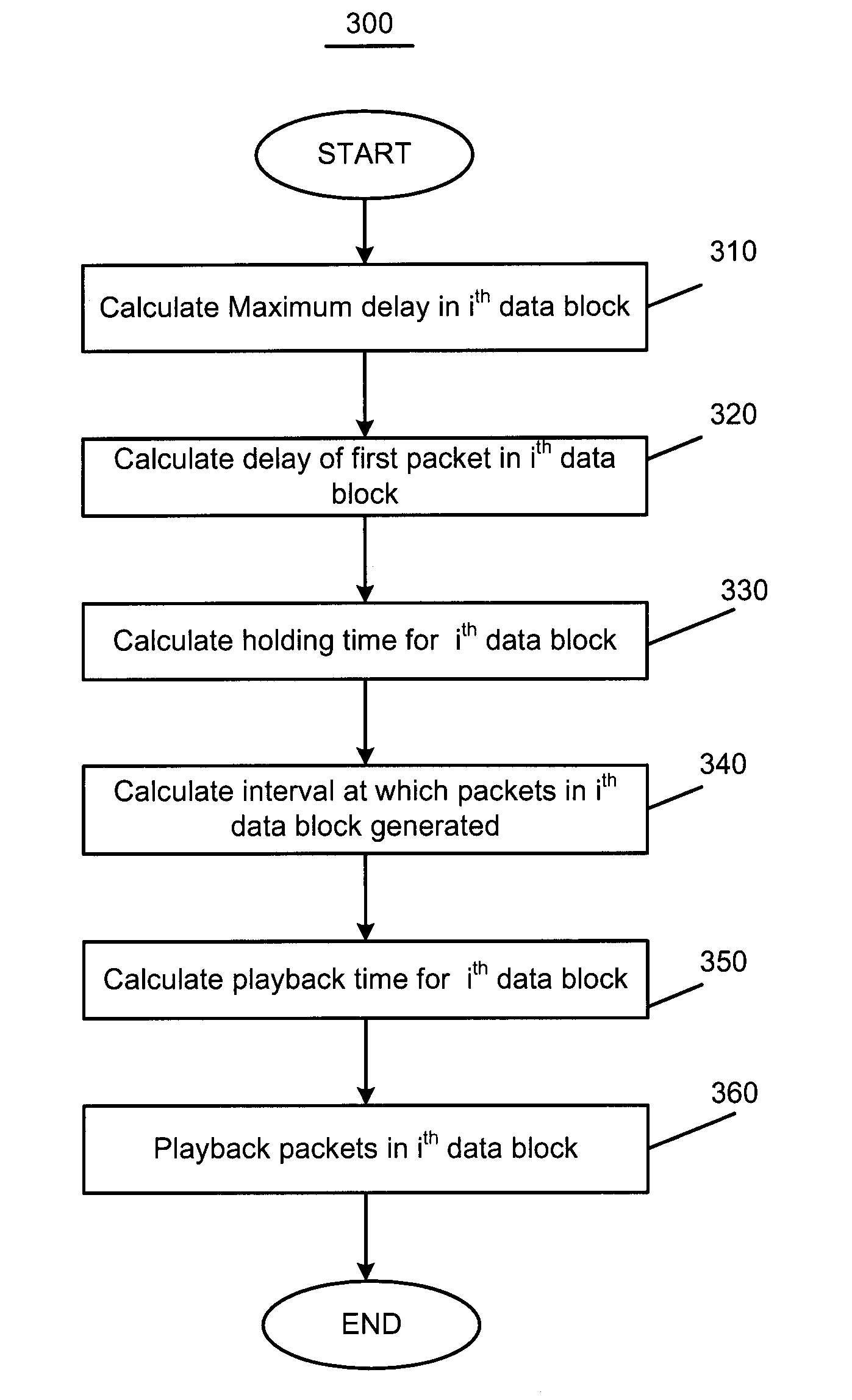
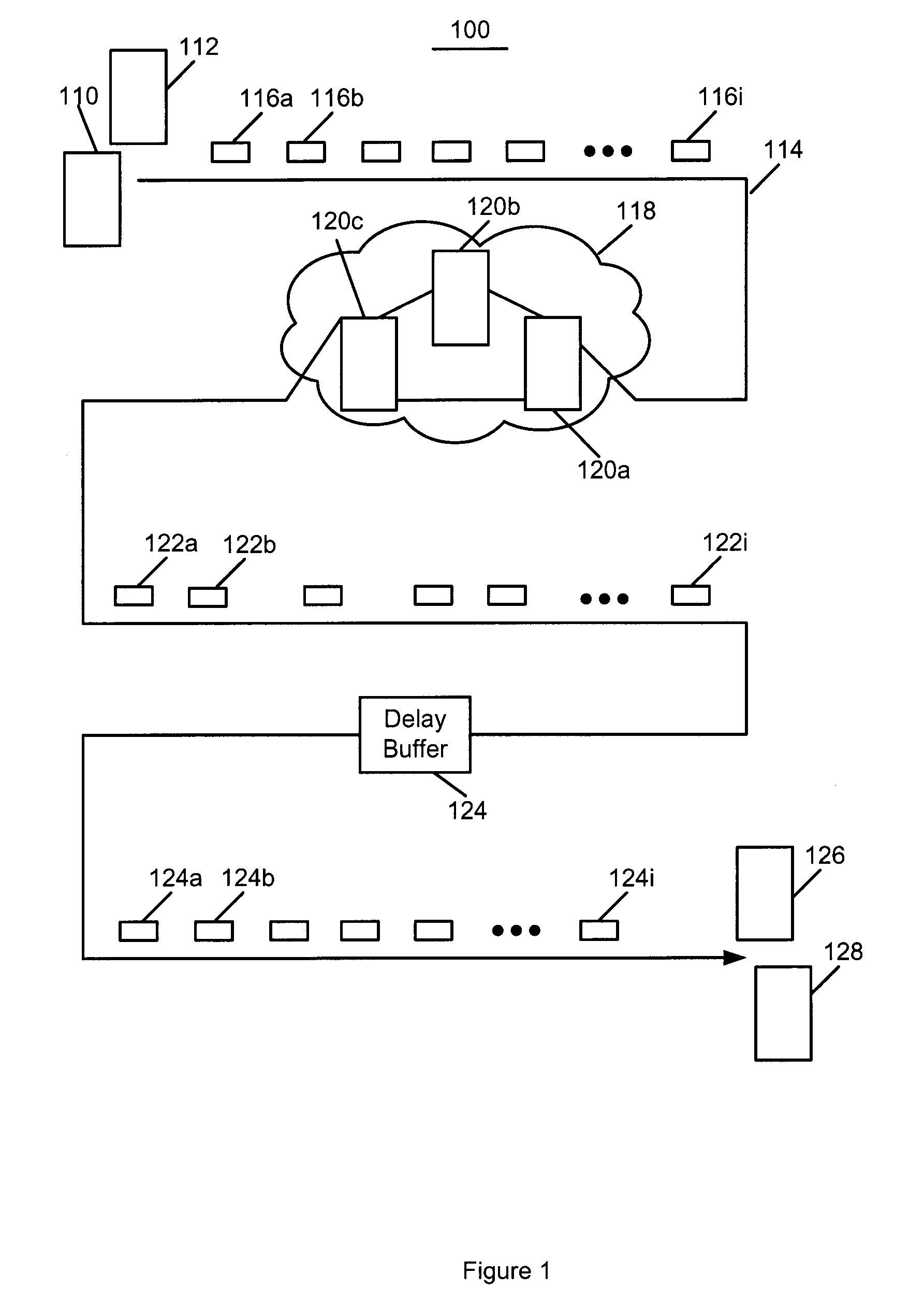
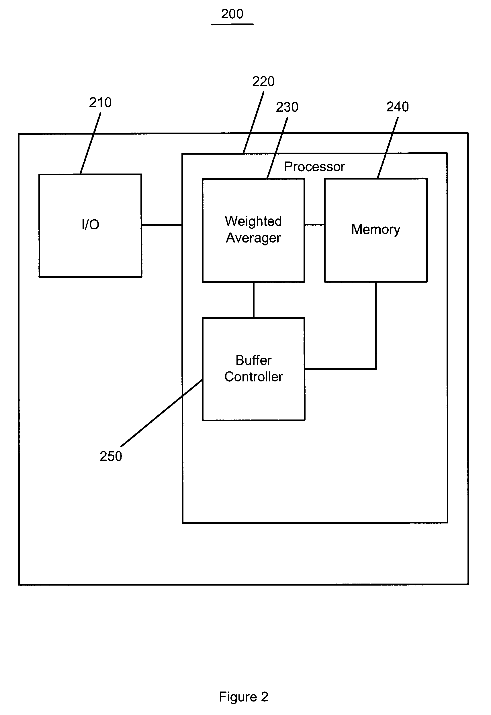
[0012]In exemplary embodiments, systems, modules, methods and / or computer readable mediums for adaptive removal of delay jitter and low end-to-end delay are provided. The embodiments calculate a holding time for holding packets in a delay buffer. The holding time is based on the end-to-end delay of the first packet provided in the network. The packets may be output from the delay buffer in the order in which the packets were input into the network. With lower end-to-end delay of the first packet, the holding time may be lower. Accordingly, the embodiments provide a flexible methodology for altering the holding time according to the network characteristics. Further, the embodiments buffer the packets for a minimal holding time that is at least as low as (or lower than) the holding time for the conventional MDV method. After being output from the delay buffer, the packets may be played back at selected playback times that are a function of the holding time, and an interval of time ove...


PUM


Abstract

Systems, modules, methods and computer readable mediums for adaptive removal of delay jitter and low end-to-end delay are provided. The method may include the following operations at a delay buffer: calculating a holding time for a plurality of packets input into a network; buffering each of the plurality of packets for the duration of the holding time; and arranging the buffered packets in a sequence indicative of an order in which the buffered packets were input into the network. The holding time may be based on a difference between a current maximum delay of the plurality of packets in a current time window and a delay of a first packet of the plurality of packets in the current time window. The method may also include playing back the buffered packets at a selected playback time. Playing back the buffered packets may be performed at a reception mechanism.

Description

BACKGROUND INFORMATION[0001]Telecommunications systems and methods transport information for applications that have different performance requirements. For example, interactive real-time applications, such as voice over Internet protocol (VoIP) and video telephony (VT), have strict end-to-end delay and delay jitter requirements. With VoIP, for example, an end-to-end delay less than 150 milliseconds (ms) may not be perceived by a human ear, delay between 150 and 300 ms may be perceptible but ideal, and delay exceeding 300 ms may be unacceptable and hinder the interactivity possible in voice communications. Therefore, a network may be configured to disregard packets having a delay greater than a selected threshold. Such a configuration may lead to packet loss and a further degradation of the network quality.[0002]End-to-end delay of packets in a network may be caused by transmission delays and / or queuing delays in routers and / or other components of the network that process the packets...

Claims


Application Information

Patent Timeline
Patent Type & Authority Patents(United States)
IPC IPC(8): G01R31/08G06F11/00H04J1/16H04J3/14
CPCH04L47/10H04L47/34H04L47/283H04L47/18
Inventor LEE, JAY J.
Owner VERIZON PATENT & LICENSING INC
Why Eureka
Try Eureka