
Heat and moisture filter exchanger and method

a filter exchanger and filter technology, applied in the field of respiratory therapy, can solve the problems of reducing the amount of oxygen received by the patient's lungs, fig. 1, affecting the efficiency of ventilation, so as to reduce the cost of selective conducting

Active Publication Date: 2011-04-12
THAYER MEDICAL CORP
View PDF3 Cites 15 Cited by
  • Summary
  • Abstract
  • Description
  • Claims
  • Application Information

AI Technical Summary

Benefits of technology

"The present invention provides a device and method for selectively conducting a stream of air produced by a ventilator through a moisturizing medium or bypassing it to prevent aerosolized medication from contacting the moisturizing medium. This reduces the risk of infection to the patient and also reduces the cost associated with the device. The device includes a housing with a ventilator-side port and a patient-side port for ventilation, and a two-way valve mechanism for selectively coupling the ventilator-side port into fluid communication with one or the other of the first and second paths. The invention also includes an external valve control for controlling the two-way valve mechanism. The moisturizing medium is disposed between the outer surface of the tube and the inner surface of the housing. The device provides a safer and more cost-effective way to ventilate patients."

Problems solved by technology

This reduces the amount of oxygen received by the patient's lungs and is always undesirable, and in some instances can be dangerous, especially for a critically ill infant being supported on a ventilator.
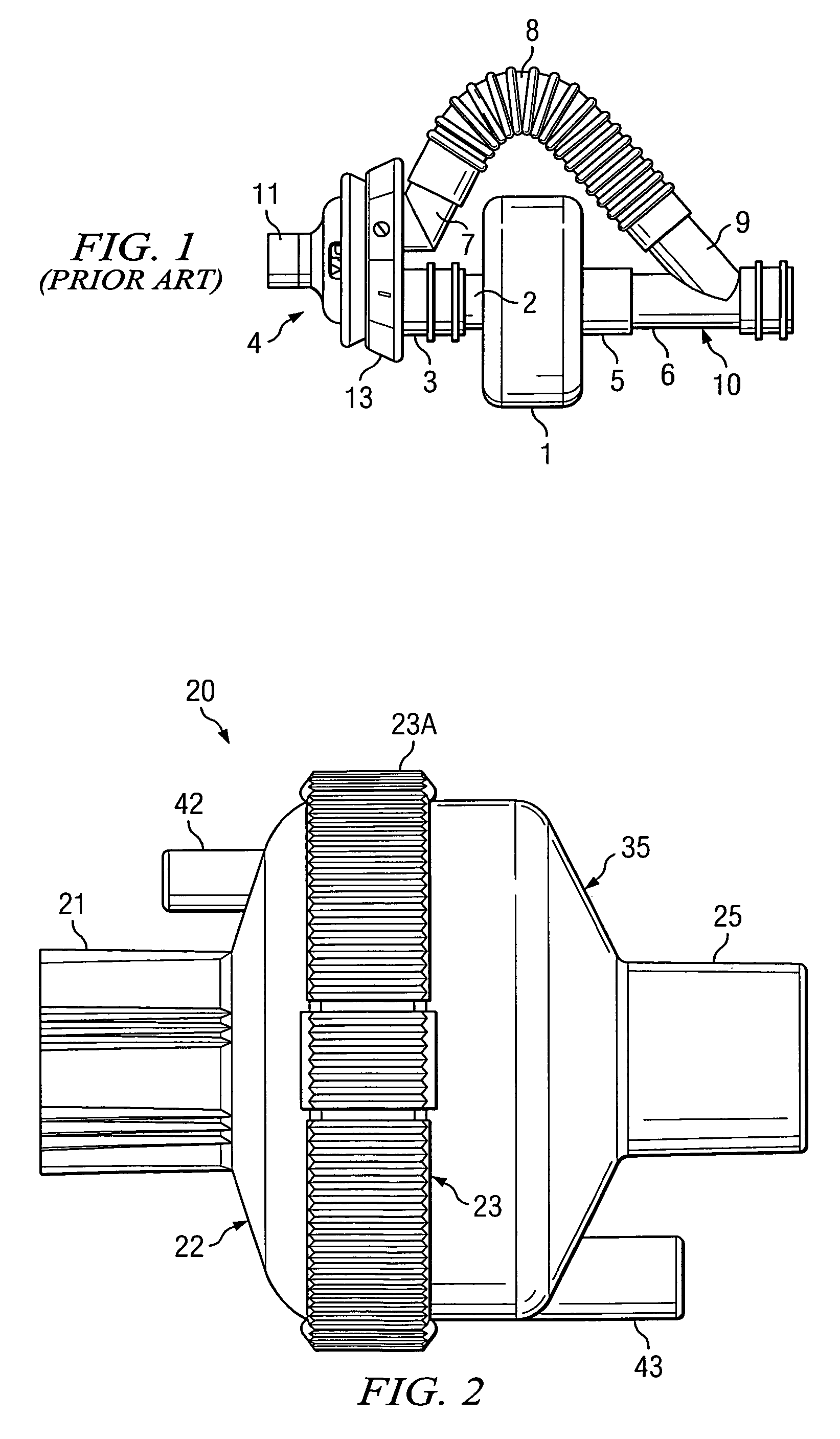
The assembly shown FIG. 1 is bulky, relatively heavy, and tends to be leaky.
Thus, there is an unmet need for a device and method for selectively conducting a stream of air produced by a ventilator through a moisturizing medium in the device or internally bypassing the moisturizing medium to prevent aerosolized medication that has been introduced into the stream from contacting the moisturizing medium.

Method used


Image

  • Heat and moisture filter exchanger and method
  • Heat and moisture filter exchanger and method
  • Heat and moisture filter exchanger and method

Examples


Embodiment Construction

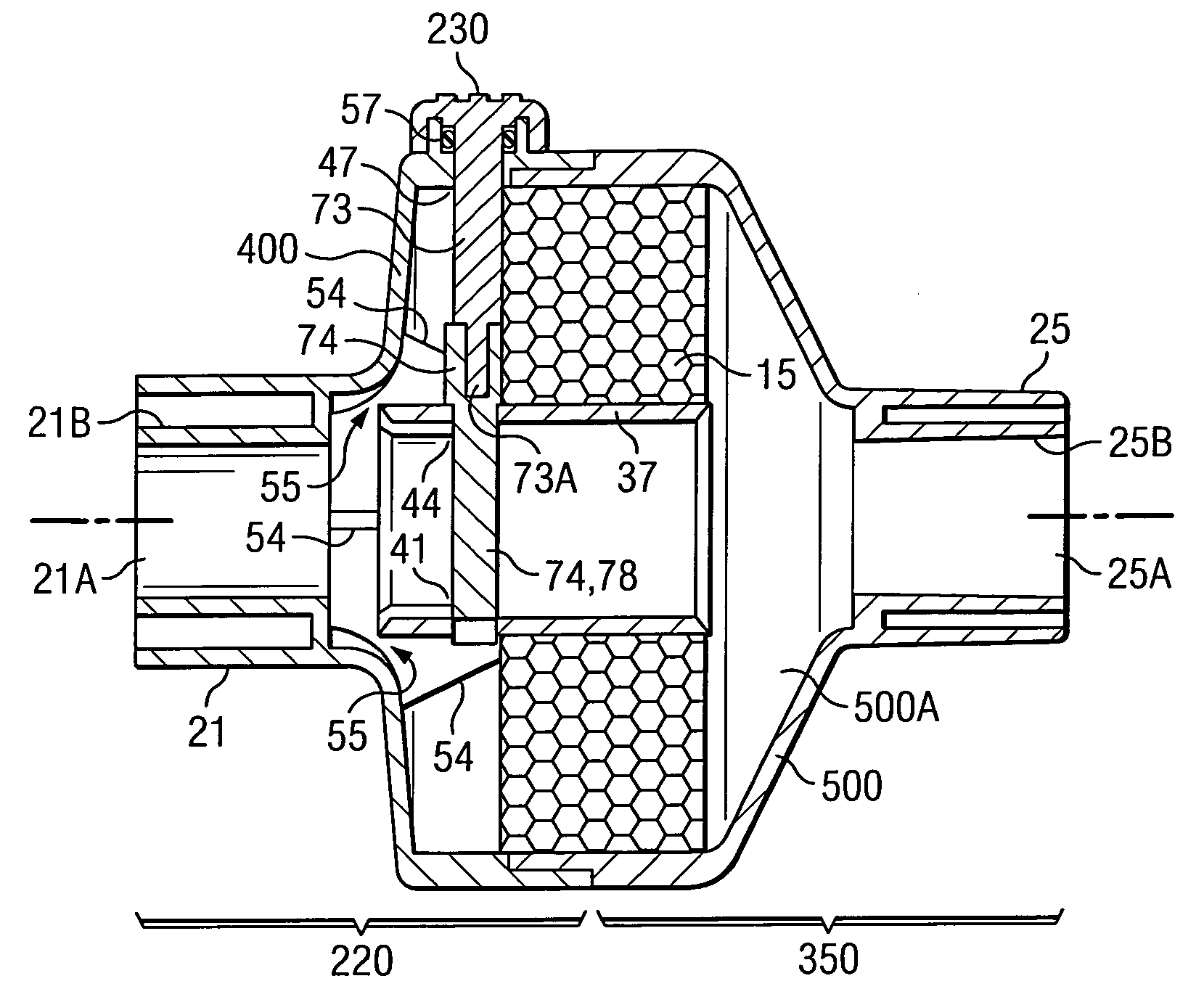
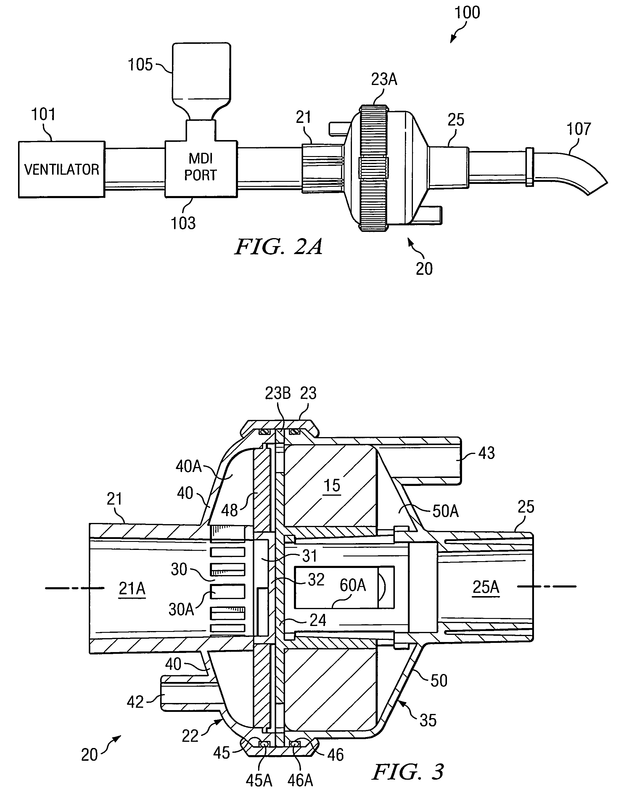
[0027]Referring to FIGS. 2, 2A and 3-6, an HME / bypass device 20 includes a ventilator-side section 22 having a ventilator-side port 21, and a patient-side section 35 having a patient-side port 25. A knurled, rotatable collar 23A of a valve plate 23 is used to control a 2-way valve located inside of a complete housing including both ventilator-side section 22 and patient-side section 35. The outer surface of ventilator-side port 21 is partially knurled, as shown. A CO2 monitoring port 42 is provided as an integral part of a ventilator-side section 22, and a drainage port 43 is provided as an integral part of patient-side section 35.

[0028]FIG. 2A shows a ventilating system 100 in which HME / bypass device 20 can be connected, wherein a ventilator 101 is coupled by suitable respiratory tubing to one port of an MDI (metered dose inhaler) injection device 103 having an opposite port connected by suitable respiratory tubing to ventilator-side port 21 of HME / bypass device 20. HME / bypass devi...


PUM


Abstract

A heat and moisture exchanger for both conducting a stream of air produced by a ventilator to a moisturizing medium and internally bypassing the moisturizing medium if aerosolized medication is introduced into the stream includes a housing having a ventilator-side port coupled to an outlet of a ventilator and a source of aerosolized medication. The housing has a patient-side port for coupling to a patient to provide ventilation including either air or air carrying aerosolized medication. A first path conducts air from the ventilator-side port through the moisturizing medium and the patient-side port, and a second path conducts air carrying aerosolized medication from the ventilator-side port directly to the patient-side port. A two-way valve mechanism in the housing selectively couples the ventilator-side port into fluid communication with one or the other of the first and second paths.

Description

CROSS REFERENCE TO RELATED APPLICATION[0001]This application is a divisional application of U.S. patent application Ser. No. 10 / 654,797 filed Sep. 4, 2003 entitled “HEAT AND MOISTURE FILTER EXCHANGER AND METHOD”, now U.S. Pat. No. 7,347,203 issued Mar. 25, 2008. That application claims the benefit of prior filed copending U.S. provisional application Ser. No. 60 / 411,213 filed Sep. 16, 2002 entitled “HEAT AND MOISTURE FILTER EXCHANGER AND METHOD” by Gregory S. Marler and David T. Sladek.BACKGROUND OF THE INVENTION[0002]The present invention relates generally to systems for respiratory therapy, particularly to ventilator systems that includes heat and moisture exchanger (HME) media or heat and moisture exchanger (HME) media in the respiratory path and also provides the additional capability of administering aerosol medication to a patient effectively without interrupting the respiratory path.[0003]The closest prior art is believed to be illustrated in FIG. 1, in which a conventional h...

Claims


Application Information

Patent Timeline
Patent Type & Authority Patents(United States)
IPC IPC(8): A62B18/08A62B9/02F28F13/12F24J3/00A61M16/00A61M15/08A61M15/00A61M16/08A61M16/10A61M16/20
CPCA61M16/08A61M16/20A61M16/1045A61M15/009A61M16/0816Y10S128/912Y10S128/911Y10S128/909A61M16/1055A61M16/106A61M16/085A61M16/201
Inventor MARLER, GREGORY S.SLADEK, DAVID T.
Owner THAYER MEDICAL CORP
Learn More