Device and method for placing within a patient an enteral tube after endotracheal intubation

a technology of endotracheal intubation and enteral tube, which is applied in the direction of catheters, other medical devices, surgery, etc., can solve the problems of occlusion of facial sinus draining tracts, perforation of throat back, and potentially serious complications of placing an ng tube through the patient's nasal passageway, so as to facilitate the placement of the intubation device and facilitate the insertion of the devi

Inactive Publication Date: 2011-04-12
KM TECH PARTNERS
View PDF89 Cites 52 Cited by
  • Summary
  • Abstract
  • Description
  • Claims
  • Application Information

AI Technical Summary

Benefits of technology

[0025]To address the forgoing problems, the present invention teaches a combination intubation device comprising: an endotracheal tube with a substantially circular cross-section, an outside diameter, an inside diameter, a proximal end and a distal end; an inflatable cuff for achieving a seal with an inner wall of the trachea of the patient positioned generally toward the distal end of the endotracheal tube; and a catheter to guide the path of an enteral tube. In a preferred embodiment, the endotracheal tube is capable of defining an arcuate path in a first geometric plane between its proximal end and its distal end to facilitate introduction of the tube into the trachea of a patient. The endotracheal tube has a wall thickness defined as the space between said outside diameter and said inside diameter. The arcuate path, when so defined, has a concave or anterior side and a convex or posterior side substantially opposite the concave side. The endotracheal tube, when so defined in the arcuate path, has a concave or anterior side and a convex or posterior side substantially opposite said concave side.
[0026]The inflatable cuff is in fluid communication with an inflation port positioned generally toward the proximal end of the endotracheal tube. The catheter preferably has a substantially circular cross-section, an outside diameter, and an inside diameter suitable to facilitate the smooth movement of the enteral tube therethrough. The enteral tube has an outside diameter of sufficient size to permit its movement through the catheter inside diameter. The catheter has a wall thickness defined as the space between said outside diameter and said inside diameter, and a length defined by a proximal end and a distal end. The catheter preferably has a first side capable of being attached to the endotracheal tube along the length of the catheter. The length of the catheter preferably extends along only a portion of the length of the endotracheal tube. The catheter has a second side substantially opposite said catheter first side. The outside diameter of the endotracheal tube has a first edge along the concave side of the defined arcuate path and a second edge along the convex side of the defined arcuate path. The distal end of the catheter is positioned to facilitate the introduction of the enteral tube into the esophagus of the patient.
[0040]In another preferred embodiment of the present invention, there is disclosed a combination medical device comprising: an endotracheal tube with a substantially circular cross-section, an outside diameter, an inside diameter, a proximal end and a distal end; and a catheter to guide the path of an enteral tube. The endotracheal tube defines an arcuate path in a first plane between its proximal end and its distal end to facilitate introduction of the tube into the trachea of a patient. The endotracheal tube employs an inflatable cuff for achieving a seal with an inner wall of the trachea of the patient positioned generally toward the distal end of the endotracheal tube, the inflatable cuff being in fluid communication with an inflation port positioned generally toward the proximal end of the endotracheal tube. The catheter has a substantially circular cross-section, an outside diameter, and an inner diameter suitable to facilitate the smooth movement of the enteral tube therethrough, and a length defined by a proximal end and a distal end. The catheter is attached to the endotracheal tube along substantially the entire length of said catheter, the proximal end of the catheter being positioned generally outside the first plane, the length of the catheter extending along only a portion of the length of the endotracheal tube. In this embodiment, the catheter defines a substantially partial-spiral path around the outside diameter of the endotracheal tube to position the distal end of the catheter in the first plane, the distal end of the catheter having a diagonal cut at the end to facilitate the introduction of the enteral tube into the esophagus of the patient. The catheter of this embodiment can also comprise a fenestration along substantially the entire length of the catheter wall to facilitate the removal from the catheter of an enteral tube having previously been placed therethrough without the need to remove the enteral tube from the patient.
[0041]The endotracheal tube of the present invention can also employ markings to assist medical personnel in ascertaining placement and positioning of the device.
[0053]When the catheter of the intubation device of the present invention includes an integrated, malleable stylet for use in shaping the intubation device, a preferred embodiment of the present inventive method can also include the additional step of: shaping the intubation device prior to inserting the device into the oral cavity of a patient so that the shape of the intubation device facilitates the insertion of the device into the oral cavity of the patient.
[0054]When the catheter of the intubation device of the present invention includes an integrated array of fiber optics capable of transmitting an optical image signal from the distal end of the device to a display device external to the patient, a preferred embodiment of the present inventive method can also include the additional step of: viewing the display of the fiber optics image signal on the display device while inserting the intubation device into the patient to facilitate placement of the intubation device.

Problems solved by technology

However, the placement of an NG tube through the patient's nasal passageway is fraught with potentially serious complications.
For example, placement of an NG tube into a patient can cause pressure necrosis of the nasal vestibule, traumatize the nasal mucosa causing massive hemorrhage, puncture the cranial vault, cause toxic shock, perforate the back of the throat, and cause occlusion of facial sinus draining tracts leading to serious infections.
Furthermore, passage of an NG tube into a patient many times is only possible by placing one's hand into the patient's posterior orpharynx to facilitate the further directing of the tube into the proximal esophagus.
Similarly, it is often difficult placing an OG tube in a patient due to problems navigating the OG tube past an obstructing tongue of the patient thereby warranting placement of the health practitioner's hand into the patient's posterior orpharynx to direct the tube into the proximal esophagus.
The conventional way of placing the NG and OG tubes after endotracheal intubation place the patient at iatrogenic risk of injury and the health practitioner / operator at risk of being bitten or exposed to enumerable infectious diseases from placing his or her hands into the patient's mouth.
A disadvantage of this device is that the airway created is temporary and not secure, and would not be used where medical judgment calls for the use of an endotracheal tube having a cuffed end that physically enters the trachea.

Method used


Image

  • Device and method for placing within a patient an enteral tube after endotracheal intubation
  • Device and method for placing within a patient an enteral tube after endotracheal intubation
  • Device and method for placing within a patient an enteral tube after endotracheal intubation

Examples


Embodiment Construction

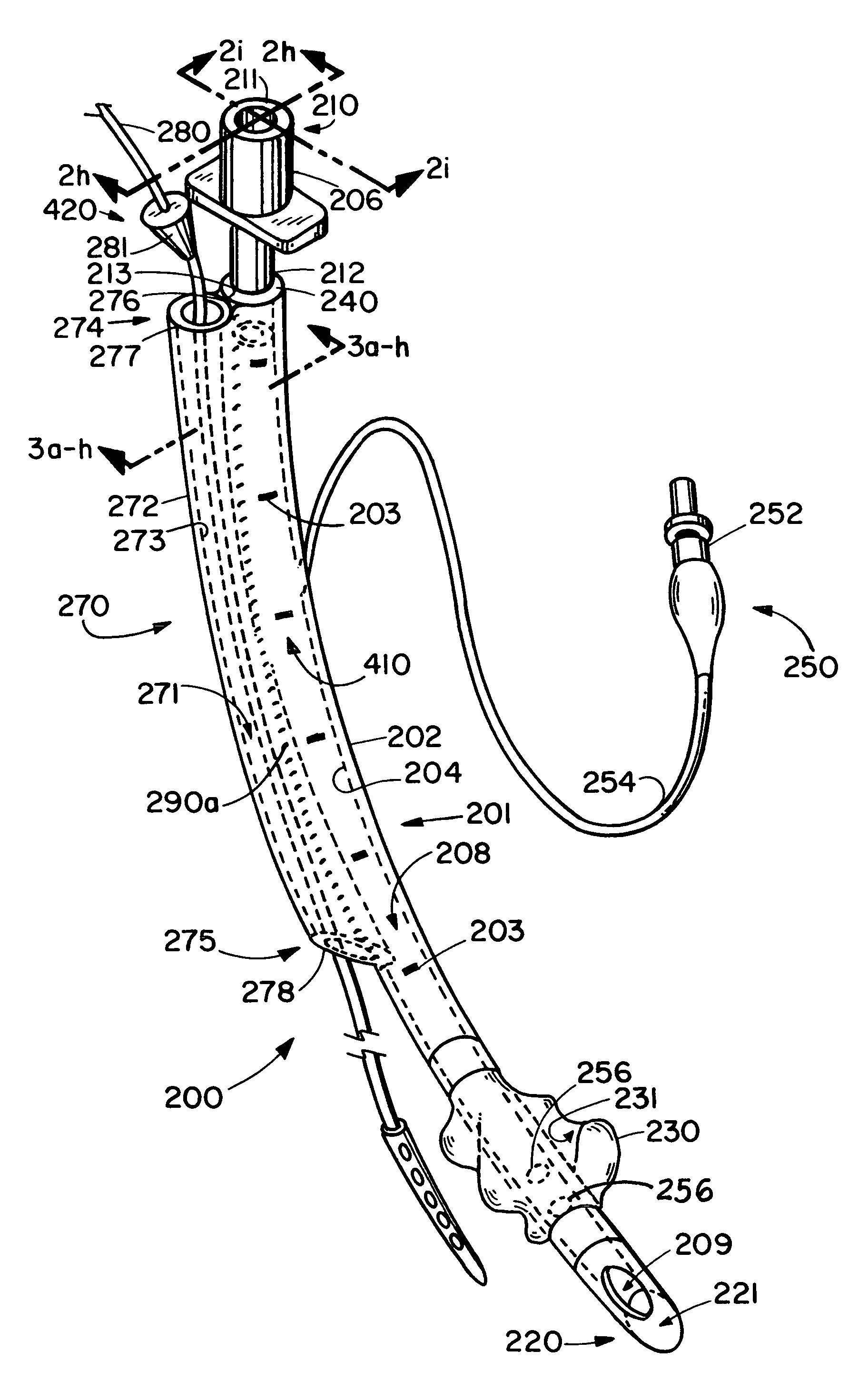
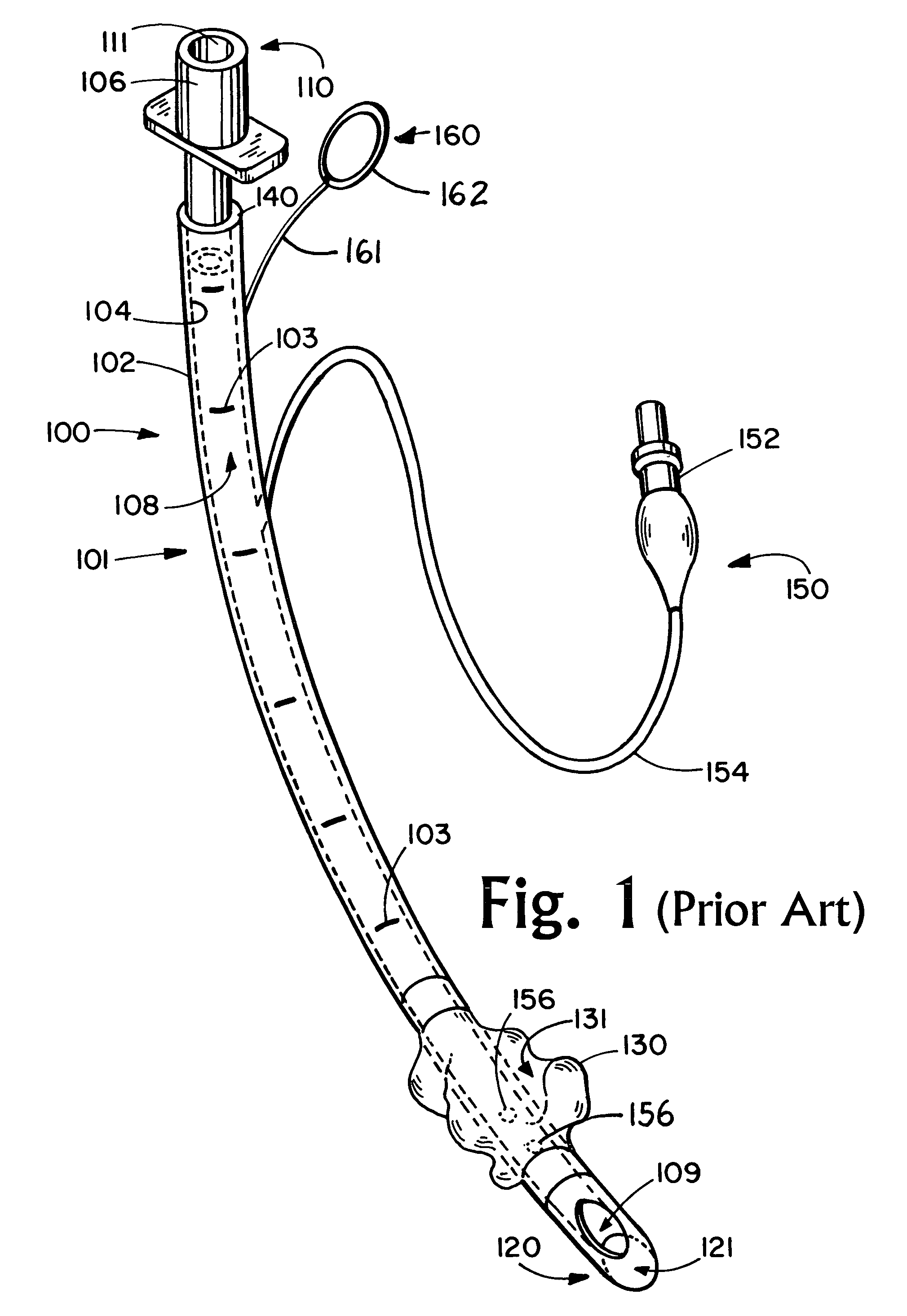
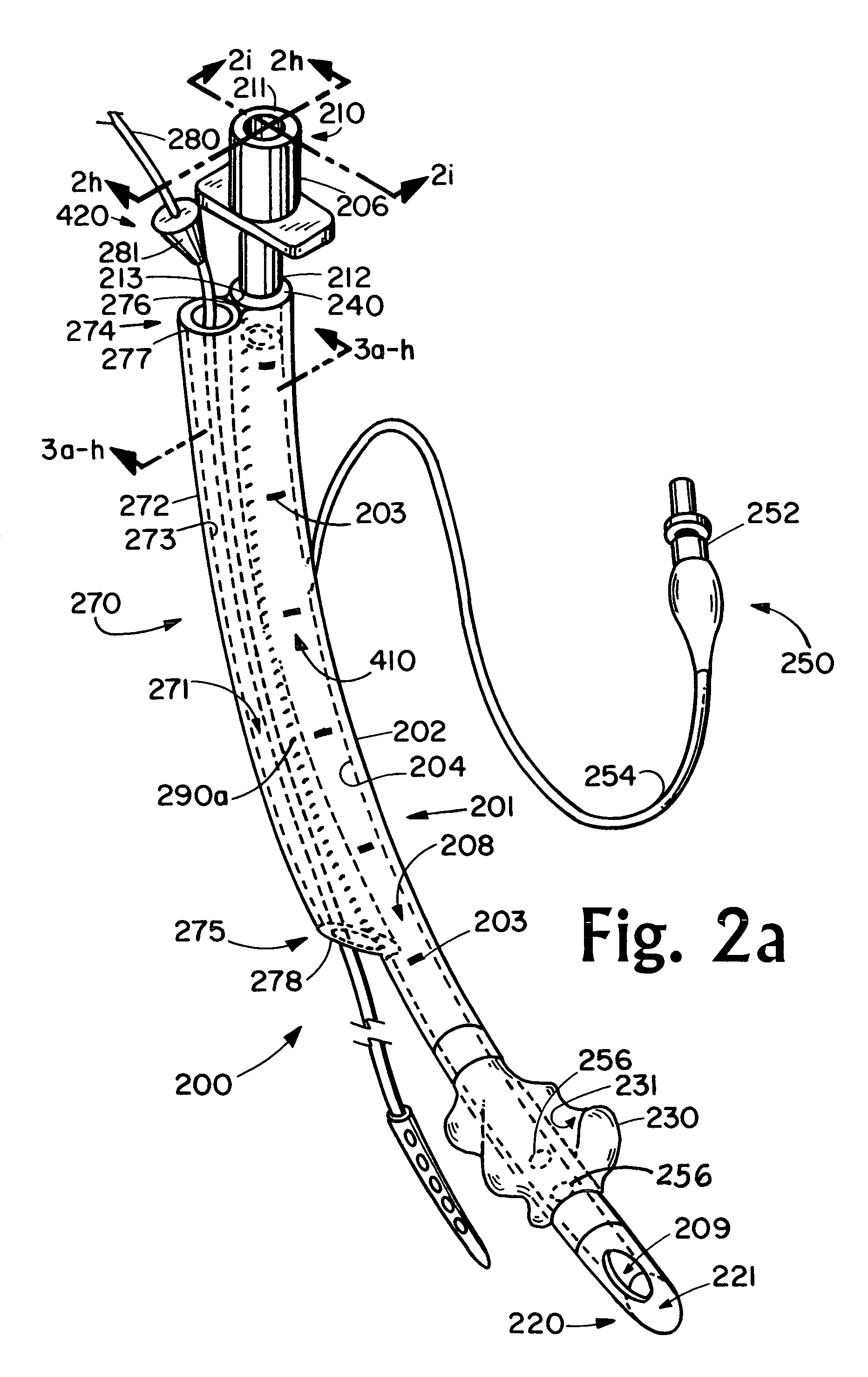
[0081]Referring now to FIG. 1, there is shown a representative endotracheal tube 100 known in the prior art having a lumen 101 having a substantially circular cross-section, an outside wall 102 having an outside wall diameter, an inside wall 104 having an inside wall diameter, a proximal end 110 and a distal end 120. The endotracheal tube 100 employs at its proximal end 110 a connector device 106 for connecting to a means of ventilation (not shown) such as ventilation source, bag valve and the like for providing a source of air to the patient's lungs through the internal conduit 108 within the lumen 101 of the endotracheal tube 100. The tube 100 has a proximal opening 111. At the distal end 120 of the endotracheal tube 100 the tube is typically bevel-shaped to facilitate introduction into the patient's trachea. Also shown in the distal region of the tube 100 is the distal opening 121 and a “Murphy's eye” suction opening 109 for suctioning fluids from below the cuff. The proximal ope...


PUM


Abstract

The present invention is directed to a novel device and method for providing a disposable endotracheal intubation device for use with an auxiliary passageway serving as a guide for the placement of an orogastic or other enterally directed device in a patient. The present invention pertains to a combination intubation device comprising an endotracheal tube and a catheter proximate the endotracheal tube to guide the path of an enteral tube. In a preferred embodiment, the endotracheal tube is capable of defining an arcuate path in a first geometric plane between its proximal end and its distal end to facilitate introduction of the tube into the trachea of a patient. In a preferred embodiment, the catheter employs a fenestration to facilitate removal of the intubation device from the patient without removal of any enteral device previously directed therethrough into the patient.

Description

CROSS-REFERENCE TO RELATED APPLICATIONS[0001]Not applicable.STATEMENT REGARDING FEDERALLY SPONSORED RESEARCH OR DEVELOPMENT[0002]Not Applicable.BACKGROUND OF THE INVENTION[0003]The present invention is directed to a novel device and method for providing a disposable endotracheal intubation device for use in conjunction with an auxiliary passageway serving as a guide for the placement of an orogastic or other enterally directed device in a patient.[0004]An early airway apparatus for assisting in artificial respiration of a patient comprised an arcuate, open-ended tubular member which was adapted to be inserted into the patient's trachea. The tubular member carried an external, inflatable resilient sleeve (cuff near the distal end thereof for affecting a seal with the inner wall of the trachea. Following the placement of this endotracheal tube (catheter) respiratory device (a procedure known as endotracheal intubation), it would often be necessary to additionally place within the pati...

Claims


Application Information

Patent Timeline
Patent Type & Authority Patents(United States)
IPC IPC(8): A61M16/00A61M31/00A61M29/00A61M25/00A61M27/00
CPCA61M16/04A61M16/0488A61M16/0486A61M16/0415A61M16/0418A61M16/0479A61M16/0434A61M2205/32
Inventor TOTZ, KENNETH A.
Owner KM TECH PARTNERS
Why Eureka
Try Eureka