Aircraft component exposed to streaming surrounding air

a technology for airframes and components, applied in the direction of airflow influencers, mechanical devices, transportation and packaging, etc., can solve the problem of perforation danger in the outer skin, and achieve the effect of preventing perforation from icing over

Inactive Publication Date: 2011-04-12
AIRBUS OPERATIONS GMBH
View PDF27 Cites 22 Cited by
  • Summary
  • Abstract
  • Description
  • Claims
  • Application Information

AI Technical Summary

Benefits of technology

[0004]One advantage of an aircraft component, such as a wing, with perforation in the outer skin for boundary layer suction, having as outer wall, an inner wall and a space defined between the outer wall and the inner wall with suction channels and pressure channels arranged alternately between the inner wall and the outer wall by partition walls, is that icing up and thus blocking of the perforations may be avoidable, even when the surface area for outflow of warm pressurized air is less than the surface area for inflow of suction air.
[0006]In one embodiment, the aircraft component designed meets the above object in that hot pressurised air, e.g. bleed air from an aircraft engine, is fed into the pressure channels and exits to the environment through the perforations in the second regions of the outer wall element. Because the second regions are considerably smaller in area than the first regions of the perforated outer wall element, which areas are connected to the suction channels, enough heat can be supplied in the outer wall element without interfering with the boundary layer suction.
[0009]According to a further embodiment, controllable valves are provided in the supply lines to the pressure channels or suction channels, by which controllable valves the negative pressure in the suction channels may be set by the control device. When substantial quantities of water arise on the outer skin, be it as a result of rain or as a result of the melting of ice, with this design the water may be prevented from being sucked into the suction pipe network as a result of excessive negative pressure in the suction channels, and icing over of the perforations may be prevented. It can be advantageous if the quantity of water arising at the outer skin is registered by suitable detectors, and if corresponding signals for controlling the negative pressure are transmitted to the control device.

Problems solved by technology

In unfavourable environmental conditions, there is a danger of the perforations in the outer skin, which perforations are used for boundary layer suction, icing up, or for an undesirable quantity of water entering the vacuum channel system that is connected to said perforations.

Method used


Image

  • Aircraft component exposed to streaming surrounding air
  • Aircraft component exposed to streaming surrounding air

Examples


Embodiment Construction

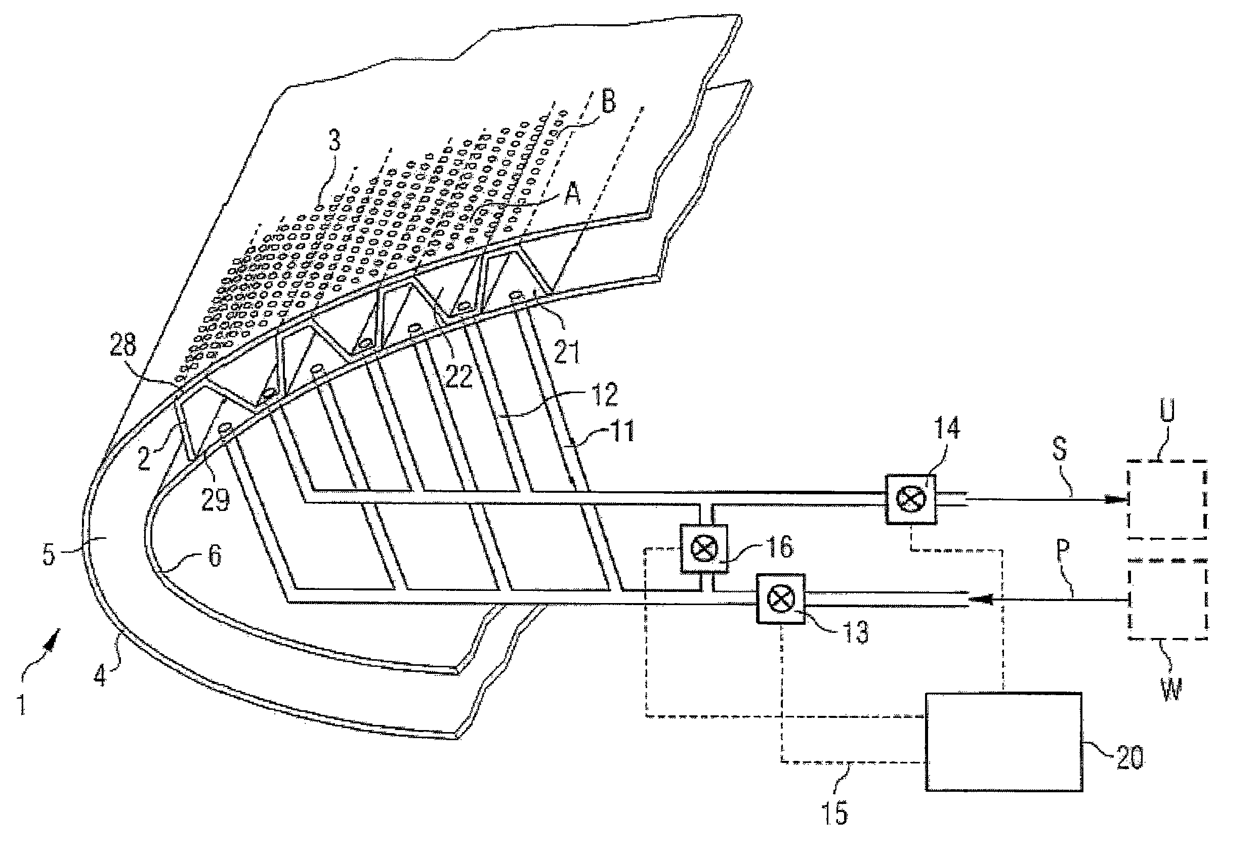
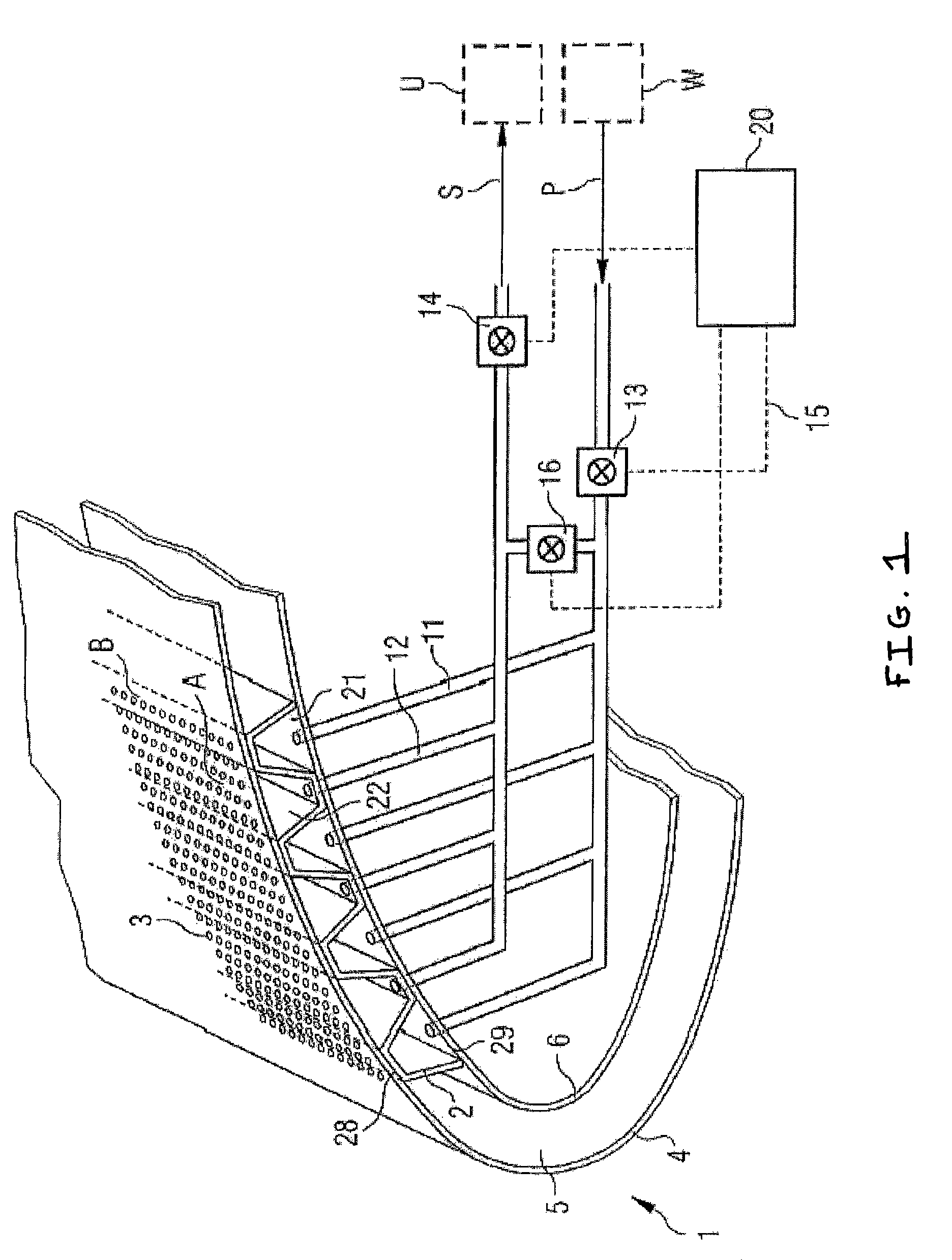
[0011]Only the air flow region of the wing 1 is shown. The wing skin is double-walled comprising an outer wall element 4 and an inner wall element 6. On its pressure side, the outer wall element 4 comprises microperforations 3. While this is not shown in the FIGURE, the microperforations 3 extend across the entire width of the wing. A sheet 2 with trapezoidal corrugations has been inserted into the space 5 between the outer wall element 4 and the inner wall element 6. The open side 29 of the trapezoidal contour of the sheet 2 with trapezoidal corrugations is several times longer than the closed baseline 28. The closed baseline 28 of the sheet 2 with trapezoidal corrugations rests against the inner surface of the outer wall element 4 and of the inner wall element 6. The regions of the sheet 2 with trapezoidal corrugations, which regions rest against the inside of the outer wall element 4, comprise openings which communicate with the microperforations 3 in the outer wall element 4.

[00...


PUM


Abstract

An aircraft component, such as a wing, has perforations through an outer wall for boundary layer suction. In the space between the outer wall and inner wall partition walls form pressure channels and suction channels that are adjacent to each other and alternate, which channels communicate with the perforations. For example, alternating channels may be formed by a corrugated structure having trapezoidal corrugations providing a larger area for the suction channels than for the pressure channels. The pressure channels may be coupled to a hot-air reservoir by a control device, lines and valves, and the suction channels may be coupled to a vacuum reservoir, unless a short-circuit valve is used to cross connect the lines.

Description

RELATED APPLICATION[0001]This application is a continuation of U.S. Non-Provisional Application No. 11 / 568,916 filed Feb. 5, 2007, which is a 371 National Stage of PCT / EP2005 / 005099 filed on May 11, 2005, which claims priority to U.S. Provisional Application No. 60 / 606,601 filed on Sep. 2, 2004 and to German Application No. 10 2004 024 007.8 filed on May 13, 2004, which are all incorporated by reference herein in their entirety.FIELD OF INVENTION[0002]The field relates to an aircraft component which is exposed to streaming surrounding air, such as a wing with perforations in the outer skin for boundary layer suction.BACKGROUND OF THE INVENTION[0003]Boundary layer suction from the surfaces of aircraft components that are exposed to streaming air is used to reduce the flow resistance and to increase the achievable lift by avoiding early change from a laminar flow to a turbulent flow. In unfavourable environmental conditions, there is a danger of the perforations in the outer skin, whi...

Claims


Application Information

Patent Timeline
Patent Type & Authority Patents(United States)
IPC IPC(8): B64C21/04B64C21/02B64D15/04F15D1/12
CPCB64C21/025B64C21/08B64D15/04B64C2230/22Y02T50/166B64C2230/06Y02T50/10
Inventor MEISTER, JUERGEN
Owner AIRBUS OPERATIONS GMBH
Why Eureka
Try Eureka