Vehicle air conditioner with defrosting operation of exterior heat exchanger

a technology of heat exchanger and vehicle, which is applied in the direction of defrosting, heating apparatus, domestic cooling apparatus, etc., can solve the problems of increased consumption power of heat pump cycle (compressor), deterioration of heat-absorbing efficiency of exterior heat exchanger, and inability to perform heating operation

Inactive Publication Date: 2002-03-28
DENSO CORP
View PDF4 Cites 42 Cited by
  • Summary
  • Abstract
  • Description
  • Claims
  • Application Information

AI Technical Summary

Benefits of technology

[0009] According to an aspect of the present invention, in a vehicle air conditioner, a heater pump cycle includes a compressor for compressing and discharging refrigerant, an interior heat exchanger for performing a heat exchange between refrigerant and air blown into a passenger compartment of the vehicle, and an exterior heat exchanger for performing a heat exchange between refrigerant and outside air outside the passenger compartment. A heat core is disposed for heating air blown into the passenger compartment by performing a heat exchange between air and a fluid which recovers waste heat generated in the vehicle. The vehicle air conditioner has frosting determination means for determining whether a surface of the exterior heat exchanger is frosted, heating capacity determining means for determining whether a heating capacity of the heater core is larger than a predetermined capacity, and a control unit for controlling operation of the heat pump cycle. In the vehicle air conditioner, at least when the frosting determination means determines a frosting on the surface of the exterior heat exchanger, and when the heating capacity determining means determines that the heating capacity of the heater core is larger than the predetermined capacity, the control unit performs a defrosting operation in which the surface of the exterior heat exchanger is defrosted. Accordingly, even in the defrosting operation, a sufficient heating can be obtained. Because the defrosting operation is performed while a sufficient heating is obtained, it can prevent the heat pump cycle from operating with a large power, and consumed power in the compressor can be reduced in the heating operation. In the present invention, when the heating capacity of the heater core is larger than the predetermined capacity, it can be determined that heating capacity of the heater core is sufficient for heating the passenger compartment.
[0010] According to an another aspect of the present invention, in a vehicle air conditioner, a ratio adjusting unit is disposed for adjusting a ratio of an air amount introduced through an inside air introduction port to an air amount introduced through an outside air introduction port, and frosting determination means for determining whether a surface of the exterior heat exchanger is frosted is provided. In this case, at least when the frosting determination means determines a frosting on the surface of the exterior heat exchanger, the control unit performs a defrosting operation in which the surface of the exterior heat exchanger is defrosted, and the ratio adjusting unit increases the ratio of the inside air amount introduced through the inside air introduction port. Accordingly, in the defrosting operation, a heat load of the heater core can be made smaller, and a sufficient heating can be obtained. That is, in the defrosting operation for defrosting the exterior heat exchanger, the heating capacity of the heater core is increased. In the present invention, the heating capacity of the heater core can be increased, by heating the fluid supplied to the heater core, by reducing a flow amount of the fluid, by increasing a rotation speed of an engine, by stopping operation of a blower for blowing outside air toward a radiator that cools the fluid, by increasing an output of a fuel cell, or the like.

Problems solved by technology

However, when the heat pump is operated while the surface of the exterior heat exchanger is frosted, heat-absorbing efficiency of the exterior heat exchanger is deteriorated.
However, a heating operation cannot be performed while refrigerant discharged from the compressor is supplied to the exterior heat exchanger (i.e., during defrosting operation).
Therefore, consumption power of the heat pump cycle (compressor) is increased.
In a vehicle, having a relatively small amount of waste heat, such as an electric vehicle, however, sufficient heating may be not obtained during the defrosting operation.

Method used


Image

  • Vehicle air conditioner with defrosting operation of exterior heat exchanger
  • Vehicle air conditioner with defrosting operation of exterior heat exchanger
  • Vehicle air conditioner with defrosting operation of exterior heat exchanger

Examples


first embodiment

[0030] (First Embodiment)

[0031] In the first embodiment, a vehicle air conditioner according to the present invention is typically used for an electric vehicle having a fuel cell (FC stack) as a power supply. The first embodiment will be now described with reference to FIGS. 1-5.

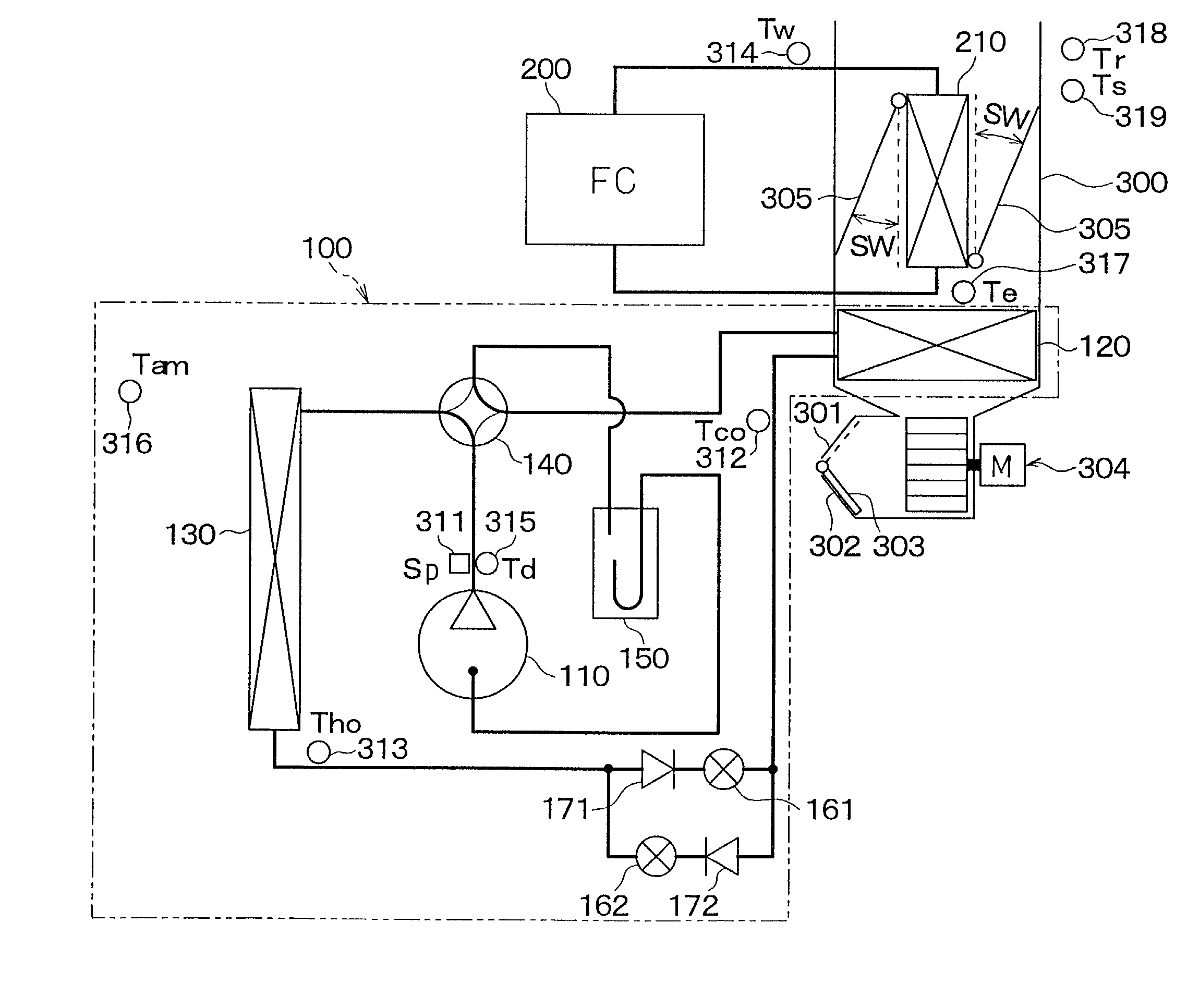
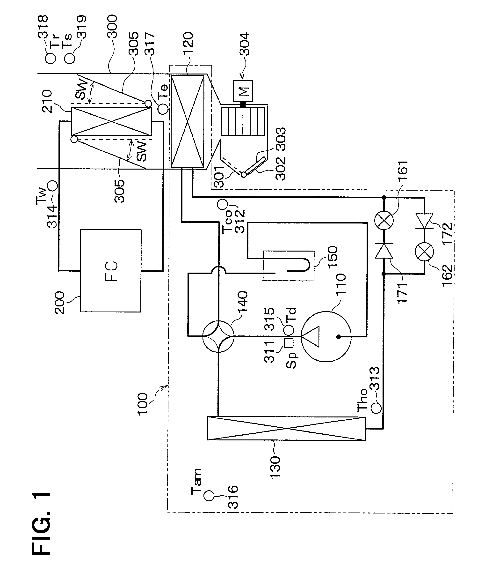
[0032] In FIG. 1, a heat pump cycle (heat pump) 100 enclosed by a two-dot chain line is disposed to switch an operation mode between a heating operation, a cooling operation and a defrosting operation, and a fuel cell (macromolecule-electrolyte type fuel cell) 200 is disposed to generate electric power by a chemical reaction between oxygen and hydrogen.

[0033] A compressor 110 (electric compressor) sucks and compresses refrigerant using an inverter control. An interior heat exchanger 120 is disposed to perform a heat exchange between refrigerant and air blown into a passenger compartment, and an exterior heat exchanger 130 is disposed to perform a heat exchange between refrigerant and outside air.

[0034] A fou...

second embodiment

[0069] (Second Embodiment)

[0070] In the second embodiment, when frosting on the surface of the exterior heat exchanger 130 is determined, when the temperature of hot water supplied to the heater core 210 is equal to or higher than the predetermined temperature and when a vehicle speed Vs is equal to or higher than a predetermined speed Vso (e.g., 11 km / hour, in the second embodiment), the defrosting operation is performed.

[0071] Accordingly, frost is melted by the defrosting operation, and the melted water drops can be blown away by vehicle travelling wind. Therefore, when the heating operation is performed again after finishing the defrosting operation, water drops (frost) melted in the defrosting operation can be prevented from being freezed again, thereby lengthening a heating operation time.

[0072] Next, operation of a vehicle air conditioner according to the second embodiment will be described with reference to the flow diagram in FIG. 6.

[0073] When the heating operation switch ...

third embodiment

[0081] (Third Embodiment)

[0082] When the vehicle speed is excessively high in defrosting operation, the exterior heat exchanger 130 is greatly cooled by vehicle travelling wind. Therefore, defrosting operation efficiency may be decreased, and power consumed in the compressor 110 for melting frost may be increased.

[0083] In the third embodiment, when the frosting on the surface of the exterior heat exchanger 130 is determined, when the temperature of hot water supplied to the heater core 210 is equal to or higher than the predetermined temperature, and when the vehicle speed Vs is higher than a first predetermined speed Vs1 (e.g., 10 km / hour in the third embodiment) and is lower than a second predetermined speed Vs2 (e.g., 40 km / hour in the third embodiment), the defrosting operation is performed.

[0084] Next, operation of a vehicle air conditioner according to the third embodiment will be described with reference to the flow diagram in FIG. 7.

[0085] When the heating operation switch ...


PUM


Abstract

In a vehicle air conditioner with a heat pump cycle having an interior heat exchanger and an exterior heat exchanger, when a frosting on a surface of the exterior heat exchanger is determined and when a temperature of hot water supplied to a heater core is equal to or higher than a predetermined temperature, the exterior heat exchanger is defrosted in a defrosting operation. Accordingly, the defrosting operation can be performed while a sufficient heating can be obtained.

Description

[0001] This application is related to and claims priority from Japanese Patent Applications No. 2000-294514 filed on Sep. 27, 2000 and No. 2001-101599 filed on Mar. 30, 2001, the contents of which are hereby incorporated by reference.[0002] 1. Field of the Invention[0003] The present invention relates to a vehicle air conditioner including a heater core that uses waste heat generated in a heat pump cycle and a vehicle as a heating source, and it is suitably applied to an electric vehicle.[0004] 2. Description of Related Art[0005] When a heating operation is performed in a conventional heat pump cycle (heat pump), it is well known that a surface of an exterior heat exchanger is frosted. However, when the heat pump is operated while the surface of the exterior heat exchanger is frosted, heat-absorbing efficiency of the exterior heat exchanger is deteriorated. In JP-A-10-166846, therefore, high-temperature refrigerant discharged from a compressor is supplied to the exterior heat exchan...

Claims


Application Information

Patent Timeline
Patent Type & Authority Applications(United States)
IPC IPC(8): B60H1/22B60H1/32F25B13/00F25B41/04F25B47/02B60H1/00
CPCF25B2700/21152B60H1/00392B60H1/3207F25B13/00F25B41/04F25B47/02F25B47/025F25B2313/0314F25B2313/0315F25B2341/0661F25B2400/04F25B2600/02F25B2600/2513F25B2700/1931F25B2700/2106B60H2001/00961F25B41/385F25B41/20B60H1/00907B60H2001/00935
Inventor ITOH, SATOSHIYAMAGUCHI, MOTOHIROTOMATSU, YOSHITAKAHIRATA, TOSHIOYAMANAKA, YASUSHIHONDA, KEITAIRITANI, KUNIO
Owner DENSO CORP
Why Eureka
Try Eureka