Head gimbal assembly of hard disk drive having support element in a bonding region of a slider

a slider and support element technology, applied in the direction of maintaining the head carrier alignment, recording information storage, instruments, etc., can solve the problems of cracking of the bond of all three samples, and achieve the effect of reducing the flexibility of the flexur

Inactive Publication Date: 2011-04-12
SAMSUNG ELECTRONICS CO LTD
View PDF7 Cites 6 Cited by
  • Summary
  • Abstract
  • Description
  • Claims
  • Application Information

AI Technical Summary

Benefits of technology

[0026]The foregoing and / or other aspects and utilities of the present general inventive concept are also achieved by providing a head gimbal assembly including a slider to lift a magnetic head from a surface of a rotating disk through a lifting force of a pressure differential generated thereby, a flexure flexibly coupled to the slider to form a bonding region, the flexure being biased in a direction to oppose the lifting force, and a support element disposed in the bonding region to decrease flexibility of the flexure therein, the support element applying a force supplemental to the to the bias on the flexure such that the lifting force lifts the slider and the support element a predetermined distance from the rotating disk.
[0027]The foregoing and / or other aspects and utilities of the present general inventive concept are also achieved by providing a hard disk drive including a disk to rotate and generate thereby a pressure differential at its surface, a head gimbal assembly including a slider to lift a magnetic head from a surface of the rotating disk through a lifting force of the pressure differential generated thereby, a flexure flexibly coupled to the slider to form a bonding region, the flexure being biased in a direction to oppose the lifting force, and a support element disposed in the bonding region to decrease flexibility of the flexure therein, the support element applying a force supplemental to the to the bias on the flexure such that the lifting force lifts the slider and the support element a predetermined distance from the rotating disk, and an actuator to position the head gimbal assembly over the rotating disk.

Problems solved by technology

However, if an impact of 1100 G is applied to the prior art HGA 10 for 1 ms, the bonds of all three samples were cracked.

Method used


Image

  • Head gimbal assembly of hard disk drive having support element in a bonding region of a slider
  • Head gimbal assembly of hard disk drive having support element in a bonding region of a slider
  • Head gimbal assembly of hard disk drive having support element in a bonding region of a slider

Examples


Embodiment Construction

[0040]Reference will now be made in detail to the embodiments of the present general inventive concept, examples of which are illustrated in the accompanying drawings, wherein like reference numerals refer to the like elements throughout. The embodiments are described below in order to explain the present general inventive concept by referring to the figures.

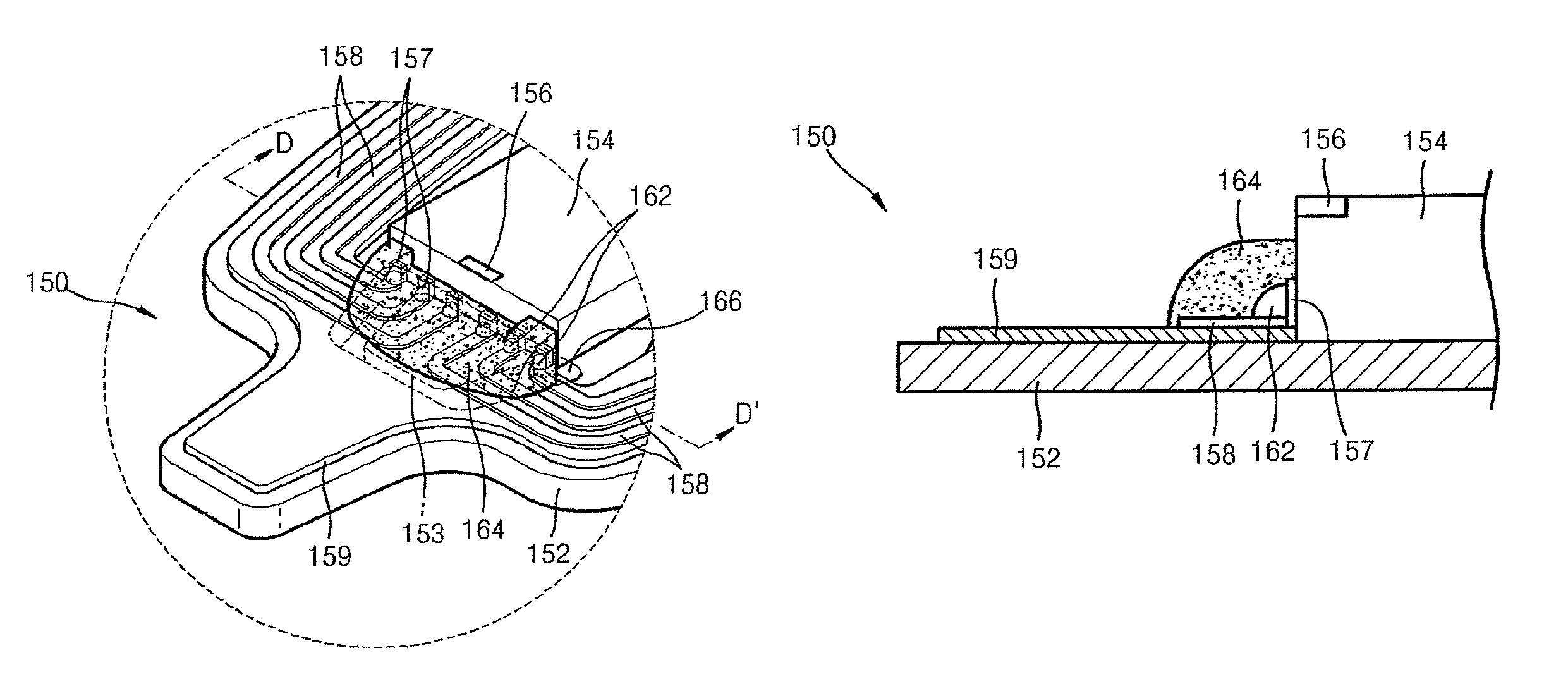
[0041]FIG. 5 is a schematic plan view of an HDD including an HGA according to an embodiment of the present general inventive concept, FIG. 6 is a perspective view of the exemplary HGA of FIG. 5, and FIG. 7 is an enlarged view of portion C of FIG. 6. It is to be understood that while the descriptions below will be confined to a single disk accessed by a single HGA, multiple disks and multiple HGAs may be incorporated without deviating from the spirit and intended scope of the present general inventive concept.

[0042]Referring to FIGS. 5 through 7, the exemplary HDD includes a disk 120 and an actuator 130. The disk 120 may be mount...


PUM

PropertyMeasurementUnit
thicknessaaaaaaaaaa
thicknessaaaaaaaaaa
thicknessaaaaaaaaaa

Abstract

A head gimbal assembly (HGA) of a hard disk drive (HDD) includes a flexure, a slider attached to the flexure and including a magnetic head, a plurality of pads at a side of the slider, a plurality of traces attached to and supported by the flexure and respectively bonded to the pads to form an electrically continuous circuit therebetween, and an insulating support element covering a bonding region between the pads and the traces.

Description

CROSS-REFERENCE TO RELATED APPLICATIONS[0001]This application claims the benefit of priority under 35 U.S.C. §119(a) of Korean Patent Application No. 10-2006-0122590, filed on Dec. 5, 2006, in the Korean Intellectual Property Office, the disclosure of which is incorporated herein by reference in its entirety.BACKGROUND OF THE INVENTION[0002]1. Field of the Invention[0003]The present general inventive concept relates to a hard disk drive (HDD), and more particularly, to a head gimbal assembly (HGA) of a HDD having a support structure disposed between a slider with a magnetic head and a supporting flexure.[0004]2. Description of the Related Art[0005]A hard disk drive (HDD) is a well-known information storage device that records data on a disk and / or reproduces data from the disk using a magnetic head. The HDD includes an actuator which moves the magnetic head to a desired position on the disk. The actuator includes a swing arm, a voice coil motor (VCM), and a head gimbal assembly (HGA...

Claims


Application Information

Patent Timeline
Patent Type & Authority Patents(United States)
IPC IPC(8): G11B5/55
CPCG11B5/4853G11B5/48G11B5/49G11B21/02G11B21/21
Inventor JEONG, KI-TAGYOO, YONG-CHULKAM, YOON-GYU
Owner SAMSUNG ELECTRONICS CO LTD
Why Eureka
Try Eureka