Method for production of a stator and stator produced according thereto

a technology of stator and stator plate, which is applied in the direction of dynamo-electric machines, electrical apparatus, magnetic circuit shape/form/construction, etc., can solve the problem of reducing the elasticity between the two end covers, and achieve the effect of greater axial rigidity

Inactive Publication Date: 2011-04-19
SEG AUTOMOTIVE GERMANY GMBH
View PDF31 Cites 3 Cited by
  • Summary
  • Abstract
  • Description
  • Claims
  • Application Information

AI Technical Summary

Benefits of technology

[0004]The method according to the present invention for manufacturing a stator for an electric machine has the advantage that because the annular lamination packet is plastically deformed in the axial direction at least in some parts of the axial end surfaces, its flexibility, particularly in the context of being screwed between two end covers, is significantly reduced, thus improving the attachment between two end covers. This significantly reduces the danger of the fasteners between the two end covers coming loose. In addition, this prevents to the greatest extent possible the electromagnetically effective inner teeth of the stator from fanning out due to clamping between the two end covers. As a result, this also reduces electromagnetic losses.
[0005]It is particularly advantageous for axial clamping surfaces to be formed onto the two axial ends of the annular lamination packet as a result of the plastic deformation. This means that the plastic deformation in the axial direction reduces the subsequent elastic component of the deformation of the stator in the axial direction. This reduces the elasticity between the two end covers. The remaining compressibility of the stator is now more homogeneous so that the stresses between the individual fastening elements between the two end covers are now considerably less divergent from one another. Particularly when manufacturing the axial clamping surfaces by means of a cold shaping process, in addition to the intentional plastic deformation, the axially exerted shaping forces also achieve an increase in the axial rigidity. This has an advantageous impact in stators installed with the axial clamping technique, which are subjected to a high pressure load in the installed state and, due to their laminated packet construction, have a seating behavior that is intrinsically unfavorable for the screw connection of the housing. This exertion of force on the finished, hollow cylindrical stator after the roller bending process sharply reduces the variation that is an inherent part of the remaining deformation. It is therefore also possible to establish even tighter tolerances for the dimensions and shape of the stator and therefore to fulfill even more exacting requirements.
[0006]According to another embodiment of the invention, at the same time as the axial deformation, the annular lamination packet is pressed in the radial direction on its outer circumference and is thus likewise plastically deformed. This measure prevents any excessive changes in the radial direction from occurring due to the axial exertion of force; the outer form of the stator yoke or stator is more precise and can thus be maintained more easily.

Problems solved by technology

This reduces the elasticity between the two end covers.

Method used


Image

  • Method for production of a stator and stator produced according thereto
  • Method for production of a stator and stator produced according thereto
  • Method for production of a stator and stator produced according thereto

Examples


Embodiment Construction

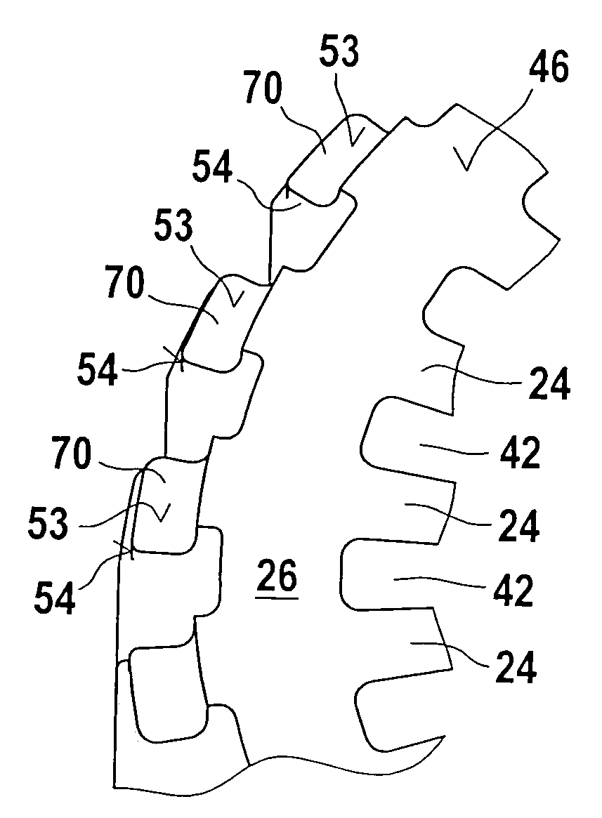
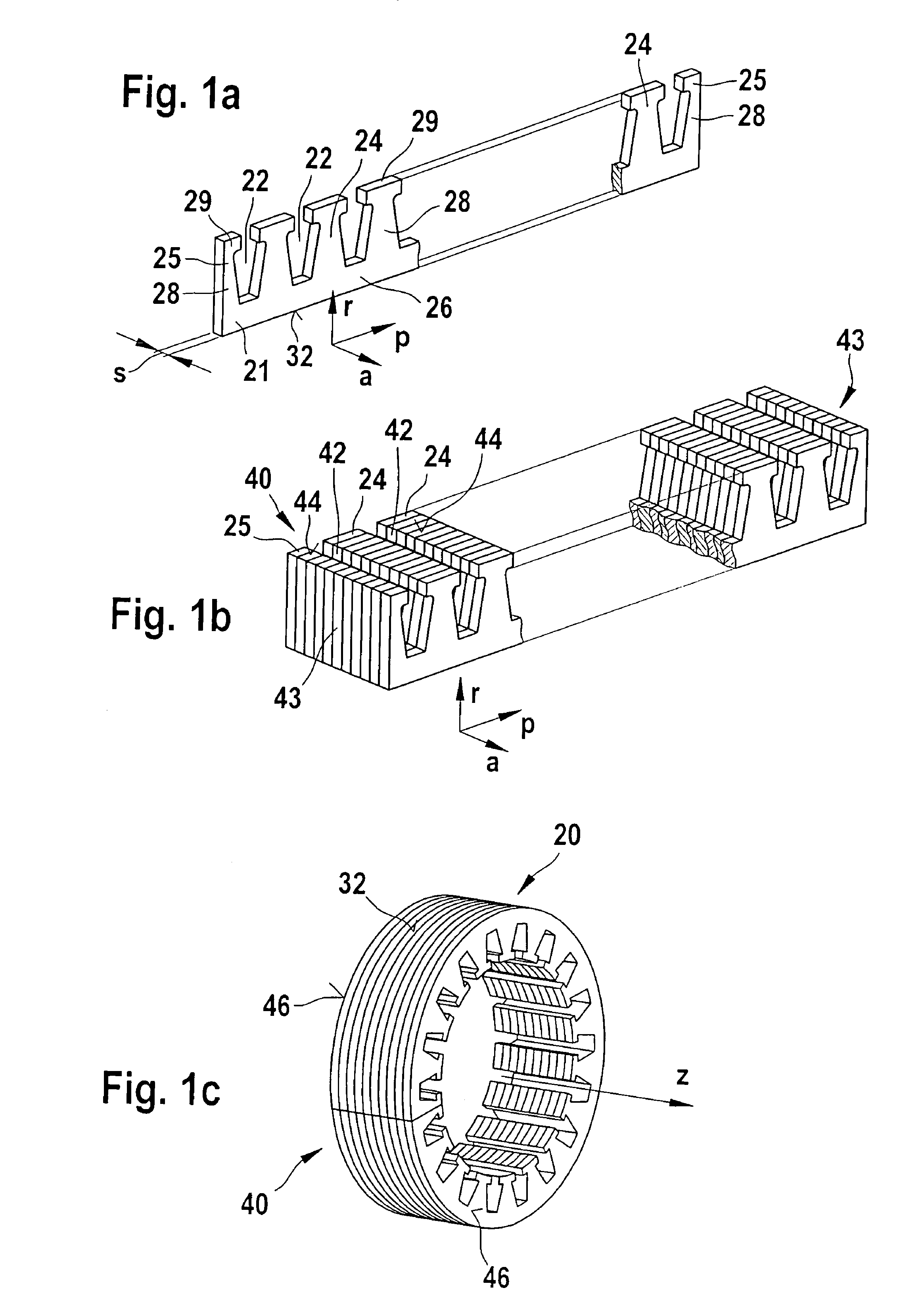
[0038]FIGS. 1a, 1b, and 1c show the basic manufacturing method of an electric machine stator core 20 manufactured using the so-called flat packet manufacturing method. First, essentially rectangular or block-shaped strip-shaped lamellas 21 are produced, which are provided with groove slots 22. The groove slots 22 are delimited on both sides by a respective tooth 24 or half tooth 25. The teeth 24 and half teeth 25 are connected to one another by means of a yoke 26. The yoke 26 extends essentially in the circumference direction p and the radial direction r and also generally has a material thickness s that coincides with a material thickness of the lamellas 21. The yoke 26 has a yoke rear surface 32 oriented away from the teeth 24 and 25. This yoke rear surface 32 is oriented in the negative direction r. The teeth 24 and half teeth 25 extend essentially in the radial direction r and the circumference direction p. The teeth 24 and 25 also have the material thickness s. Like the teeth 2...


PUM

PropertyMeasurementUnit
thicknessaaaaaaaaaa
thicknessaaaaaaaaaa
thicknessaaaaaaaaaa

Abstract

A method for manufacturing a stator core (20) for an electric machine, in which a plurality of strip-shaped laminations (21) are first stacked to form an essentially block-shaped lamellas packet (40) that is then shaped into an annular form by means of roller bending in one of the subsequent steps so that the outer teeth are provided on the outer circumference of the lamination packets and has an axial direction (a) that corresponds to a cylinder axis (z), the annular form having axial end surfaces (46), wherein in another of the subsequent steps, the annular lamination packet (40) is plastically deformed in the axial direction (a) only on the outer teeth (70) of the axial end surfaces (46).

Description

CROSS-REFERENCE[0001]The invention described and claimed hereinbelow is also described in German Patent Application DE 10 361 857.0 filed on Dec. 30, 2003. This German Patent Application, whose subject matter is incorporated here by reference, provides the basis for a claim of priority of invention under 35 U.S.C. 119(a)-(d).BACKGROUND OF THE INVENTION[0002]The invention relates to a method for manufacturing a stator and stator manufactured according to said method.[0003]WO 01 / 54254 A1 has disclosed a method for manufacturing a stator that is provided for an electric machine, in particular for a generator used in motor vehicles. In it, strip-shaped lamellas are first stacked to form an essentially block-shaped lamination packet that is then shaped into an annular form by means of roller bending in one of the subsequent steps. The annular form of this stator or stator yoke has two axial end surfaces. It has been determined that such stators or stator yokes that are axially clamped by...

Claims


Application Information

Patent Timeline
Patent Type & Authority Patents(United States)
IPC IPC(8): H02K15/02H02K15/14H02K1/14H02K1/16
CPCH02K1/16H02K15/024Y10T29/49009
Inventor RAU, EBERHARDBERGER, THOMASHENNE, MARTINPFLUEGER, KLAUS
Owner SEG AUTOMOTIVE GERMANY GMBH
Why Eureka
Try Eureka