
Hybrid method for estimating the ground effect on an aircraft

a ground effect and hybrid technology, applied in the direction of instruments, structural/machine measurement, golf clubs, etc., can solve the problems of inability to give direct measurements, relatively inaccurate and unreliable corresponding measurements, and the current reliability and accuracy of digital assessmen

Active Publication Date: 2011-04-19
AIRBUS OPERATIONS (SAS)
View PDF12 Cites 5 Cited by
  • Summary
  • Abstract
  • Description
  • Claims
  • Application Information

AI Technical Summary

Benefits of technology

The present invention provides a method for assessing the aerodynamic ground effect on an aircraft by determining the variation of at least one aerodynamic coefficient of the aircraft as a function of the height, for a range of heights extending from an aerodynamically infinite height to a zero height. The method involves subdividing the range of heights into at least two consecutive sets of heights, and determining the variation of the aerodynamic coefficient for each set using either wind tunnel tests or digital simulation. The method allows for a harmonious combination of computations and tests, and reduces the weight of the wall corrections in the ground effect compared to conventional methods. The method also allows for the incorporation of physical principles and easy incorporation in current processes.

Problems solved by technology

Such an experimental assessment has the drawback that the correction level provided by said correction coefficients is generally high in relation to the measured values of said aerodynamic coefficient, mainly at the center of said stream, such that the corresponding measurements are relatively inaccurate and unreliable.
Such an experimental assessment cannot therefore give direct measurements of the ground effect, at the point where the latter is precisely at its most intense.
However, such a digital assessment has not currently proved reliable enough and accurate enough to be able to do away with wind tunnel tests in the intermediate part of the range of heights at which the measurements are carried out.

Method used


Image

  • Hybrid method for estimating the ground effect on an aircraft
  • Hybrid method for estimating the ground effect on an aircraft
  • Hybrid method for estimating the ground effect on an aircraft

Examples


Embodiment Construction

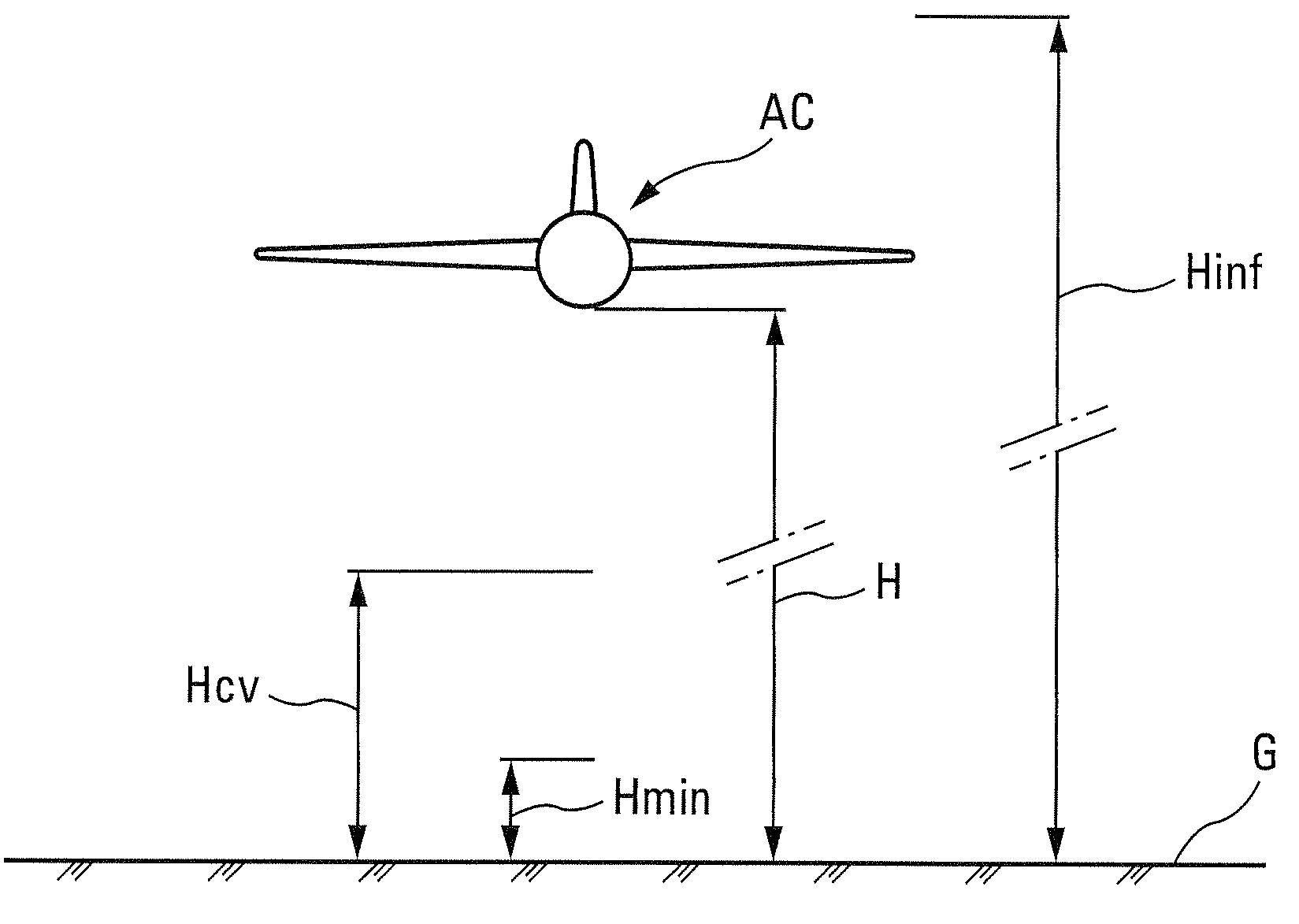
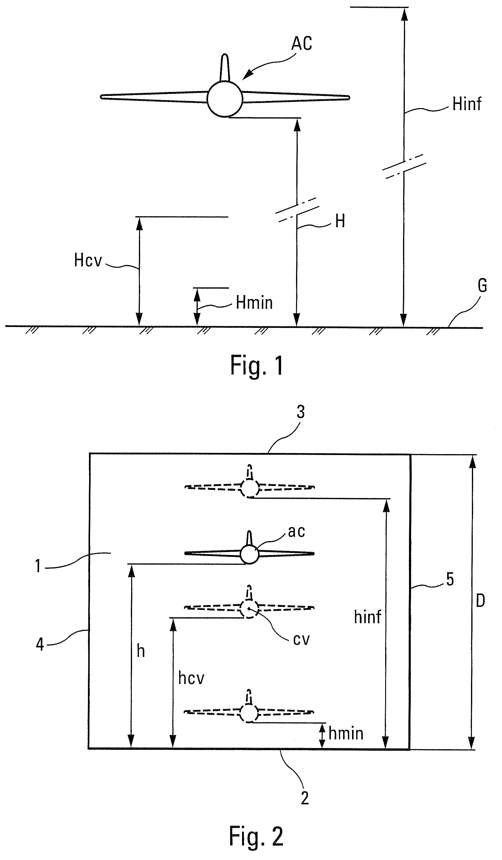
[0030]FIG. 1 diagrammatically shows, from the front, an airplane AC above the ground G. The height H of the airplane AC relative to the ground G can vary from an infinite value Hinf, at which the aerodynamic ground effect is zero or negligible, to the zero value (the airplane AC is taxiing on the ground G) for which the aerodynamic ground effect is generally maximum.

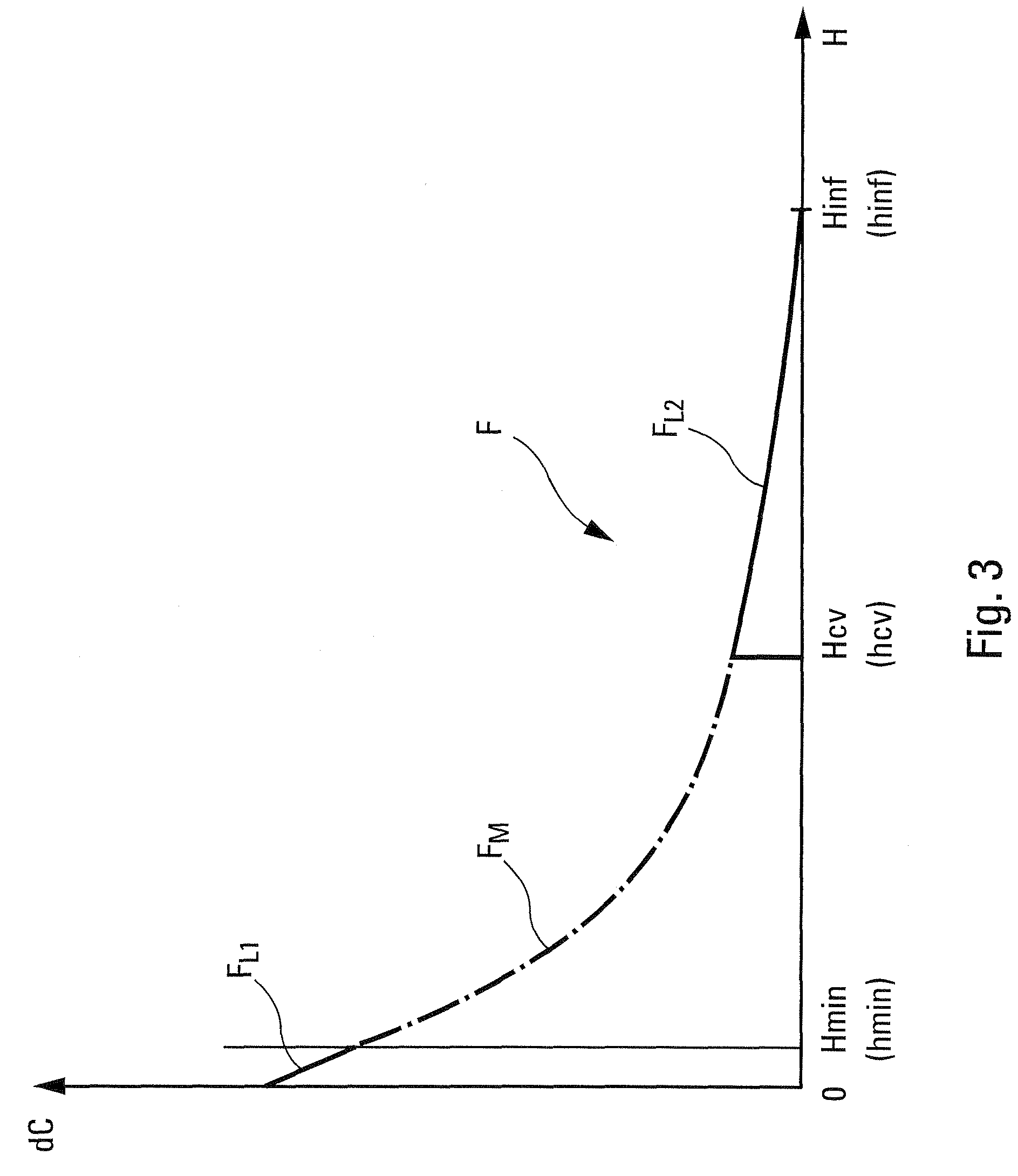
[0031]To assess said aerodynamic ground effect, it is normal to determine the variation of at least one aerodynamic coefficient of said airplane AC, for example the buoyancy coefficient Cz, the drag coefficient Cx, the pitching moment coefficient Cm, and so on, between said infinite height Hinf and said zero value. Hereinbelow, in particular with regard to FIG. 3, said aerodynamic coefficient is designated by C and its variation by dC.

[0032]Also normally, to determine the variation dC of the aerodynamic coefficient C, a model ac of the airplane AC is established and positioned in a wind tunnel airstream 1 limited by a fl...


PUM


Abstract

A method for assessing the aerodynamic ground effects on an aircraft. The method includes determining the variation of at least one aerodynamic coefficient of the aircraft as a function of the height for a range of heights extending from an aerodynamically infinite height to a zero height. In the method, (i) the range of heights is subdivided into at least two consecutive sets of heights; (ii) for one of the sets of heights, the variation of said aerodynamic coefficient is determined by wind tunnel tests using a model of the aircraft; and (iii) for the other of the sets of heights, the variation of said aerodynamic coefficient is determined by digital simulation reproducing by computation the physical reality of the air flow around said aircraft.

Description

CROSS-REFERENCE TO RELATED APPLICATION[0001]This application claims the benefit of French Patent Application 08 03428, filed on Jun. 19, 2008, which is hereby incorporated by reference.BACKGROUND OF THE INVENTION[0002]The present invention relates to a method for assessing the aerodynamic ground effect on an aircraft. For such an assessment, it is already known to determine the variation of at least one aerodynamic coefficient, such as the buoyancy coefficient, the drag coefficient, the pitching moment coefficient, etc., as a function of the height of the aircraft, in a range of height values between a value that is sufficiently high for the ground effect to be zero or negligible (value generally referred to as “infinite height” by aerodynamics engineers) and a zero value for which the aerodynamic ground effect is generally maximum, since the aircraft is taxiing on the ground.DESCRIBED OF THE PRIOR ART[0003]To do this, it is normal to perform an experimental assessment of said aerod...

Claims


Application Information

Patent Timeline
Patent Type & Authority Patents(United States)
IPC IPC(8): G01M9/06G01P13/00
CPCG01M9/06G01M9/02
Inventor CALMELS, BENOIT
Owner AIRBUS OPERATIONS (SAS)
Learn More