Screwdriver with ratchet mechanism

a screwdriver and ratchet technology, applied in the field of screwdrivers, can solve the problems of increased cost, increased risk of getting stuck and malfunctioning, and errors in the specification of the slots, and achieve the effects of saving labor costs, avoiding swaying or wobbling, and convenient and inexpensive design

Inactive Publication Date: 2011-04-19
HU BOBBY
View PDF13 Cites 22 Cited by
  • Summary
  • Abstract
  • Description
  • Claims
  • Application Information

AI Technical Summary

Benefits of technology

[0011]The switch member is pivotably mounted to the first body. The switch member is pivotable to selectively urge at least one of each pair of the engaging members for selectively engaging at least one of the engaging portions of each pair of engaging members with the teeth of the second body, thereby controlling relative rotation between the first body and the second body.
[0012]Since the transverse receiving sections extend through the first body, two elongate mold cores can be placed into a cavity of a mold, with two ends of each elongate mold core being reliably supported by the mold without the risk of swaying or wobbling while forming the first body. Errors in the specification of the transverse receiving sections will not occur during manufacture, and subsequent processing of the transverse receiving sections is not required. A useful and inexpensive design is thus provided.
[0013]Further, since four engaging members are used to engage with the teeth of the second body, the screwdriver may bear higher torque during use.
[0018]Preferably, the first body further includes a recessed section having two ends. The switch member includes a protrusion abutting against one of the ends of the recessed section for preventing excessive rotation of the switch member.
[0034]Preferably, the first body includes a recessed section having two ends. The switch member includes a protrusion abutting against one of the ends of the recessed section for preventing excessive rotation of the switch member.
[0041]By such an arrangement, subsequent processing of the receiving section is not required while providing higher torque capacity.

Problems solved by technology

When molten metal is filled into the cavity, the mold cores sway and wobble due to high temperature and high pressure in the mold such that errors are incurred in the specification of the slots.
Namely, if the slots are not processed subsequently, the movement of the detents in the slots would not be smooth, leading to risks of getting stuck and malfunction.
The cost is thus increased.
Further, only two detents are used, and only one of them is engaged with the teeth of the cylindrical rotary seat such that the detent might slide relative to the teeth or the detent and / or the teeth might be damaged when a large torque is applied to the screwdriver.
Hence, such a screwdriver can only be driven by a small torque, leading to limited application of the screwdriver, and if in any event a torque exceeds what the screwdriver can withstand, the detent which moved to a position in engagement with the teeth would be pushed out of the slot by the teeth.
But, it is noticed that this invention has a practical difficulty because in operation when the control ring is rotated counterclockwise, the upper right and bottom left stir bars cause the upper right and bottom left detents to disengage or separate from the wall of the space and coact with the teeth, and even worse, after subsequent direction changes the detents will not mesh with the teeth correctly.
Likewise, when the control ring is rotated clockwise, the upper left and bottom right stir bars would cause the upper left and bottom right detents to disengage from the wall of the space and coact with the teeth, leading to incorrect meshing after subsequent direction changes.

Method used


Image

  • Screwdriver with ratchet mechanism
  • Screwdriver with ratchet mechanism
  • Screwdriver with ratchet mechanism

Examples


Embodiment Construction

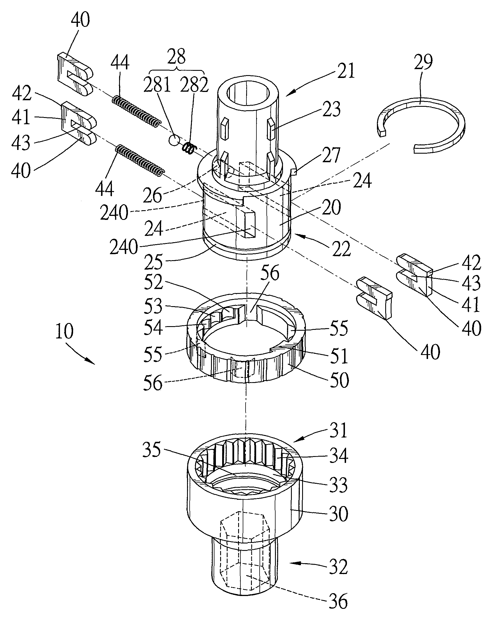
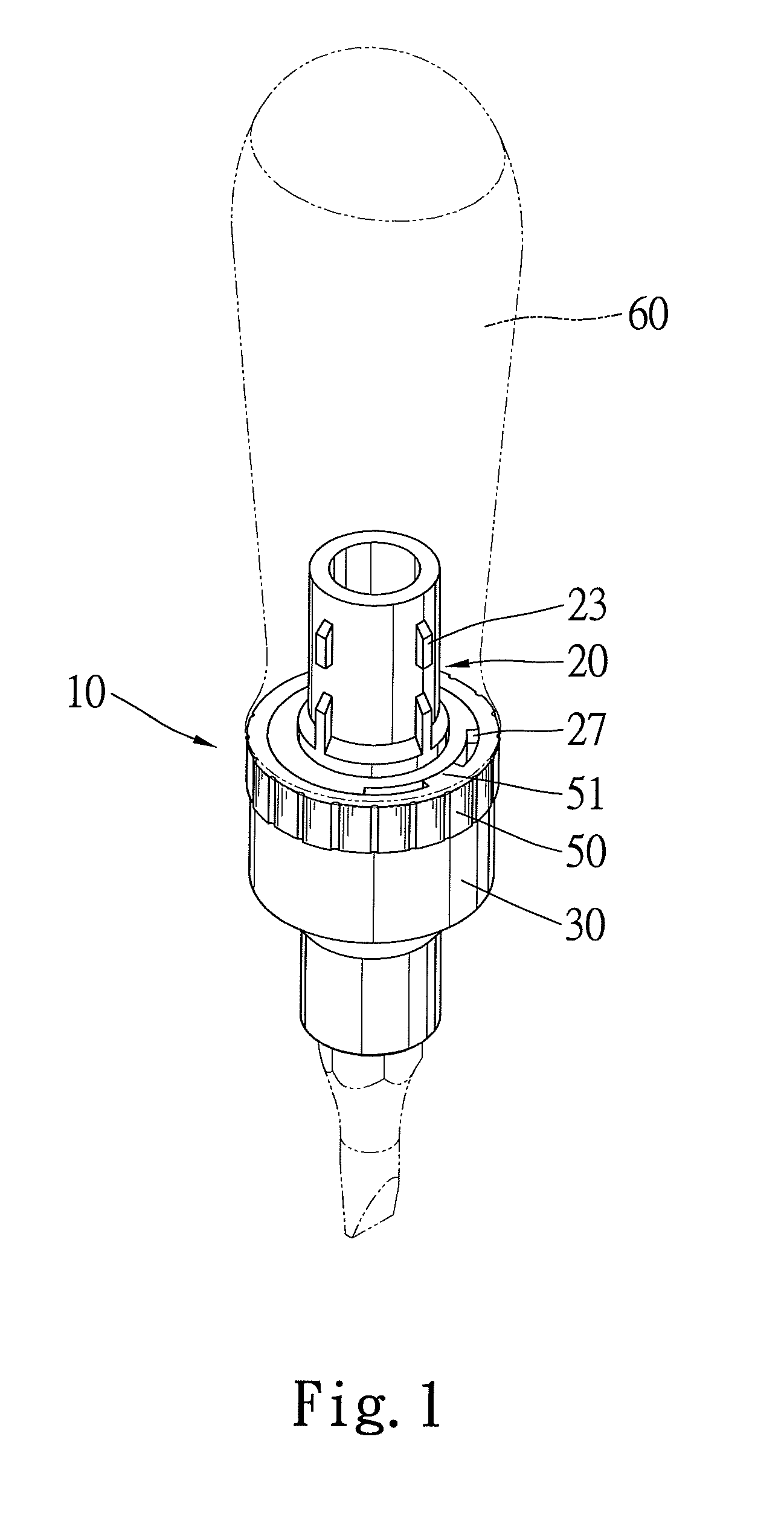
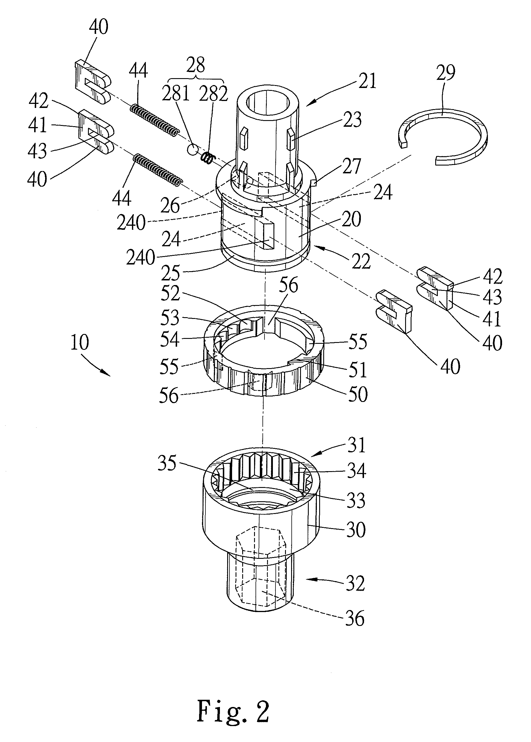
[0064]Referring to FIGS. 1 and 2, a screwdriver 10 in accordance with the present invention comprises a first body 20, a second body 30, two pairs of engaging members 40, and a switch member 50. The second body 30 is rotatably coupled to an end of the first body 20. The engaging members 40 are slidably mounted in the first body 20 and restrained and controlled by the switch member 50 pivotally mounted around the first body 20, thereby selectively restraining rotation of the second body 30.

[0065]More specifically, the first body 20 includes a first end 21 and a second end 22. A handle 60 is coupled to the first end 21 of the first body 20. Ribs or hooks 23 may be formed on the first end 21 of the first body 20 to avoid undesired detachment of the handle 60. Two transverse receiving sections 24 extend through the second end 22 of the first body 20 and each includes two end openings 240 in an outer circumference of the second end 22 of the first body 20, with the end openings 240 being...


PUM


Abstract

A screwdriver includes a first body having an end for coupling with a handle, a second body rotatably coupled to the other end of the first body, two pairs of engaging members, and a switch member pivotably mounted to the first body. Each pair of engaging members is slidably received in an associated transverse receiving section that includes two end openings in an outer circumference of the first body. Each engaging member includes a first end with an engaging portion. An elastic element is mounted between second ends of each pair of engaging members for biasing the pair of engaging members away from each other. The switch member is pivotable to selectively engage at least one of the engaging portions of each pair of engaging members with teeth of the second body, thereby controlling relative rotation between the first body and the second body.

Description

CROSS REFERENCE[0001]The present application is a continuation-in-part application of U.S. patent application Ser. No. 11 / 681,450, filed on Mar. 2, 2007 now abandoned, of which the entire disclosure is incorporated herein.BACKGROUND OF THE INVENTION[0002]1. Field of the Invention[0003]The present invention relates to a screwdriver. More particularly, the present invention relates to a screwdriver of the type with a ratchet mechanism allowing a change in the driving rotational direction for driving a screw and in a free rotational direction not driving the screw.[0004]2. Description of the Related Art[0005]U.S. Pat. No. 6,047,802 discloses a ratchet driving mechanism for a screwdriver. The ratchet driving mechanism includes a main body having two slots. A detent is received in each slot. The detents are selectively biased outward by springs to engage with teeth of a cylindrical rotary seat, thereby allowing a change in the driving rotational direction for driving a screw and in a fre...

Claims


Application Information

Patent Timeline
Patent Type & Authority Patents(United States)
IPC IPC(8): B25B15/04
CPCB25B15/04B25B13/465
Inventor HU, BOBBY
Owner HU BOBBY
Why Eureka
Try Eureka