Vehicle seat

a seat and seat back technology, applied in the field of vehicle seats, can solve the problem of restricted rearward movement of the seat back, and achieve the effect of simple structure and quick support of the head of the occupan

Active Publication Date: 2011-04-19
SUBARU CORP +1
View PDF13 Cites 40 Cited by
  • Summary
  • Abstract
  • Description
  • Claims
  • Application Information

AI Technical Summary

Benefits of technology

[0012]The present invention provides a vehicle seat having a headrest, which has a simple structure compared with a headrest drive, and supports quickly the head of an occupant when a vehicle is bumped from behind.
[0014]According to the invention, when a vehicle is bumped from behind, the detachable portions are detached from a plane spring structure or a seat back frame by the load applied from an occupant to the seat back. Therefore, the rearward movement of the seat back is restricted, and an occupant's head can contact the headrest within a short time. The rearward movement of the occupant's head is quickly stopped by the headrest. The vehicle seat of the invention is simple in the structure compared with a headrest drive, and quickly holds an occupant's head.

Problems solved by technology

Therefore, the rearward movement of the seat back is restricted, and an occupant's head can contact the headrest within a short time.

Method used


Image

  • Vehicle seat
  • Vehicle seat
  • Vehicle seat

Examples


Embodiment Construction

[0025]An embodiment of the invention will be explained hereinafter with reference to FIG. 1 to FIG. 6.

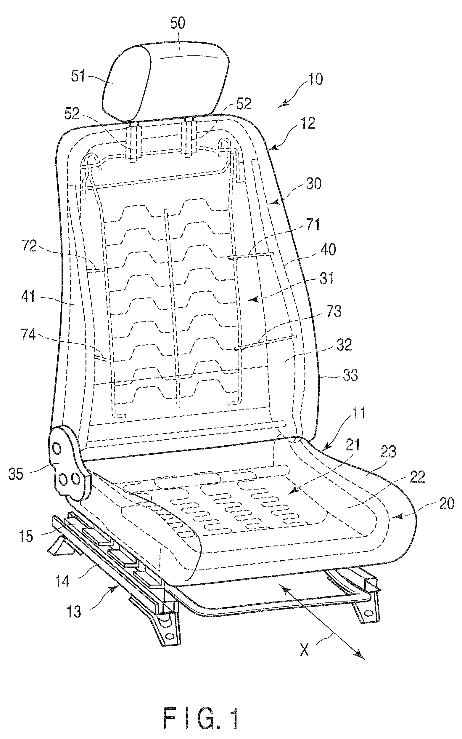
[0026]FIG. 1 shows a vehicle seat 10. The vehicle seat 10 comprises a seat cushion 11, and a seat back 12 provided at the rear of the seat cushion 11. A slide mechanism 13 is provided on the lower side of the seat cushion 11. The slide mechanism 13 has a fixed rail 14, a movable rail 15, and a lock mechanism (not shown). The fixed rail 14 is fixed to the floor of a vehicle (not shown). The movable rail 15 is movable in the longitudinal direction of a vehicle with respect to the fixed rail 14. The lock mechanism has a function to fix the movable rail 15 to the fixed rail 14. In FIG. 1, the longitudinal direction of a vehicle is indicated by the arrow X.

[0027]The seat cushion 11 comprises a seat cushion frame 20, a spring unit 21, a pad member 22, and a cover member 23. The spring unit 21 includes S-springs secured to the seat cushion frame 20. The pad member 22 is provided on the spr...


PUM


Abstract

A seat back has a seat back frame, a plane spring structure, and a headrest provided at the upper end of a seat back frame. The plane spring structure has left and right side wires, and horizontal wires extending in the horizontal direction. Connection wires are provided between the seat back frame and plane spring structure. First end portions and second end portions of the connection wires function as detachable portions. At least one of these detachable portions is detached from the seat back frame or plane spring structure by the load applied to the seat back, when a vehicle is bumped from behind.

Description

CROSS-REFERENCE TO RELATED APPLICATIONS[0001]This application is based upon and claims the benefit of priority from prior Japanese Patent Application No. 2007-284262, filed Oct. 31, 2007, the entire contents of which are incorporated herein by reference.BACKGROUND OF THE INVENTION[0002]1. Field of the Invention[0003]The present invention relates to a vehicle seat having a headrest.[0004]2. Description of the Related Art[0005]There has been proposed a headrest drive capable of moving a headrest forward to hold an occupant's head when a vehicle is bumped from behind. For example, Jpn. Pat. Appln. KOKAI Publication No. 11-268566 (patent document 1) discloses a conventional headrest drive, in which a connection member is arranged in the lower part of a bracket to support a stay of a headrest. The connection member is provided with a pressure-receiving member. In this conventional example, when an occupant is pressed to a seat back upon a collision, the pressure-receiving member is press...

Claims


Application Information

Patent Timeline
Patent Type & Authority Patents(United States)
IPC IPC(8): B60N2/42A47C7/02
CPCB60N2/4228B60N2/427B60N2/72B60N2/42781B60N2/42745
Inventor CHIDA, JUNOKAMOTO, KAZUKIMUNEMURA, NOZOMUMATSUMOTO, ATSUO
Owner SUBARU CORP
Why Eureka
Try Eureka