LED illumination device and light engine thereof

a technology of led illumination device and led light engine, which is applied in the direction of semiconductor devices for light sources, lighting and heating apparatus, and light support devices. it can solve the problems of large amount of heat generated, metal heat sinks, and inability to meet the heat dissipation requirements of high brightness led illumination devices

Inactive Publication Date: 2011-04-19
HON HAI PRECISION IND CO LTD
View PDF5 Cites 50 Cited by
  • Summary
  • Abstract
  • Description
  • Claims
  • Application Information

AI Technical Summary

Benefits of technology

[0005]Conventional heat dissipation devices, such as heat sinks, are usually made of copper, aluminum, or their alloy, and have a relatively high heat conductivity coefficient. The heat sink generally includes a base attached to the LED illumination device and a plurality of fins extending from the base for increasing a heat dissipating area of the heat sink. During operation, heat generated by the LED illumination device is conducted to the base and then distributed to the fins for dissipation. However, for obtaining a high brightness LED illumination device, a large amount of LEDs are packaged in a single LED illumination device, and thus a large amount of heat is generated during operation of the high brightness LED illumination device. The conventional metal heat sinks, which transfer heat via heat conduction means, can no longer satisfy the heat dissipation requirement of the high brightness LED illumination device.
[0005]Conventional heat dissipation devices, such as heat sinks, are usually made of copper, aluminum, or their alloy, and have a relatively high heat conductivity coefficient. The heat sink generally includes a base attached to the LED illumination device and a plurality of fins extending from the base for increasing a heat dissipating area of the heat sink. During operation, heat generated by the LED illumination device is conducted to the base and then distributed to the fins for dissipation. However, for obtaining a high brightness LED illumination device, a large amount of LEDs are packaged in a single LED illumination device, and thus a large amount of heat is generated during operation of the high brightness LED illumination device. The conventional metal heat sinks, which transfer heat via heat conduction means, can no longer satisfy the heat dissipation requirement of the high brightness LED illumination device.
[0005]Conventional heat dissipation devices, such as heat sinks, are usually made of copper, aluminum, or their alloy, and have a relatively high heat conductivity coefficient. The heat sink generally includes a base attached to the LED illumination device and a plurality of fins extending from the base for increasing a heat dissipating area of the heat sink. During operation, heat generated by the LED illumination device is conducted to the base and then distributed to the fins for dissipation. However, for obtaining a high brightness LED illumination device, a large amount of LEDs are packaged in a single LED illumination device, and thus a large amount of heat is generated during operation of the high brightness LED illumination device. The conventional metal heat sinks, which transfer heat via heat conduction means, can no longer satisfy the heat dissipation requirement of the high brightness LED illumination device.

Problems solved by technology

However, for obtaining a high brightness LED illumination device, a large amount of LEDs are packaged in a single LED illumination device, and thus a large amount of heat is generated during operation of the high brightness LED illumination device.
The conventional metal heat sinks, which transfer heat via heat conduction means, can no longer satisfy the heat dissipation requirement of the high brightness LED illumination device.

Method used


Image

  • LED illumination device and light engine thereof
  • LED illumination device and light engine thereof
  • LED illumination device and light engine thereof

Examples


Embodiment Construction

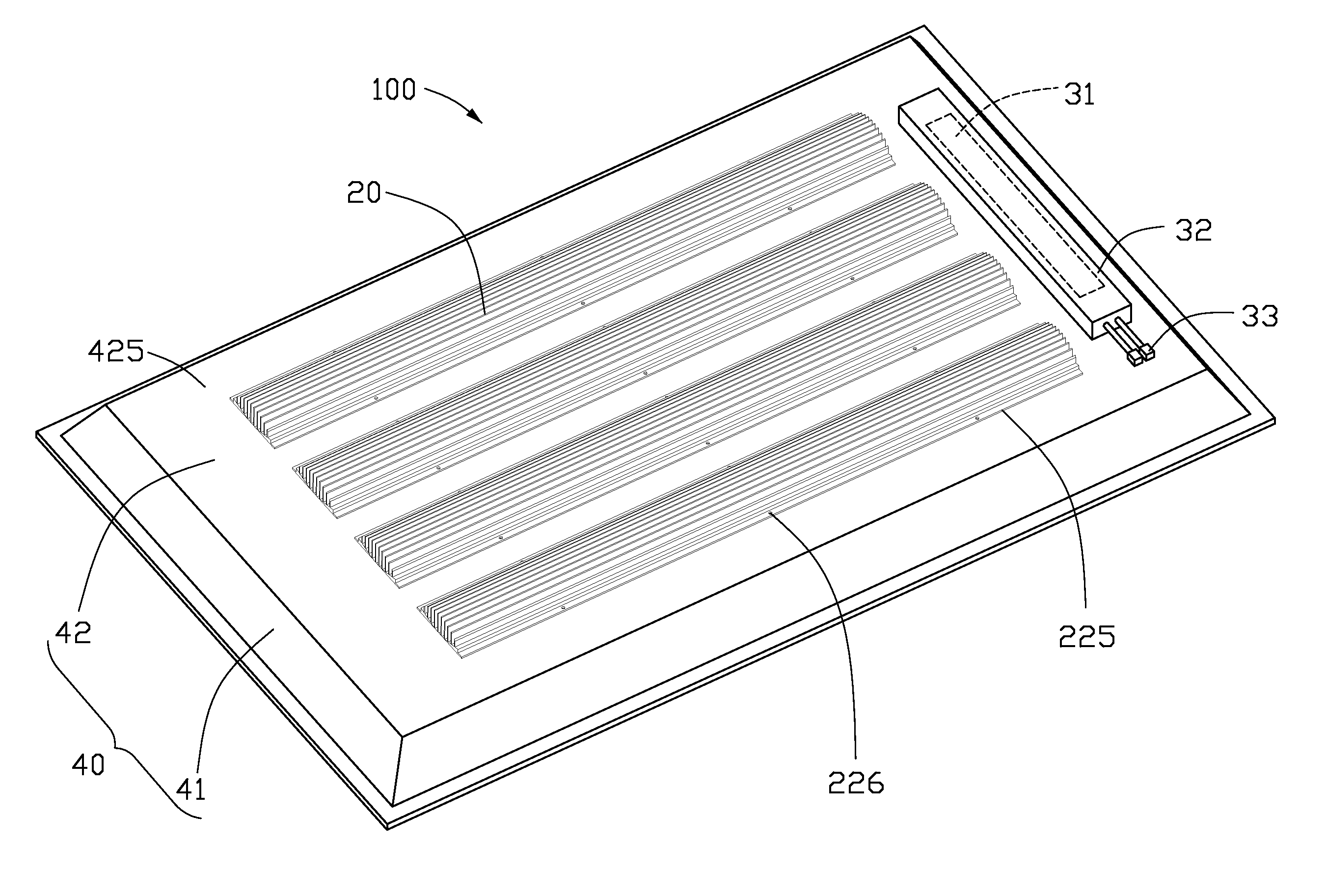
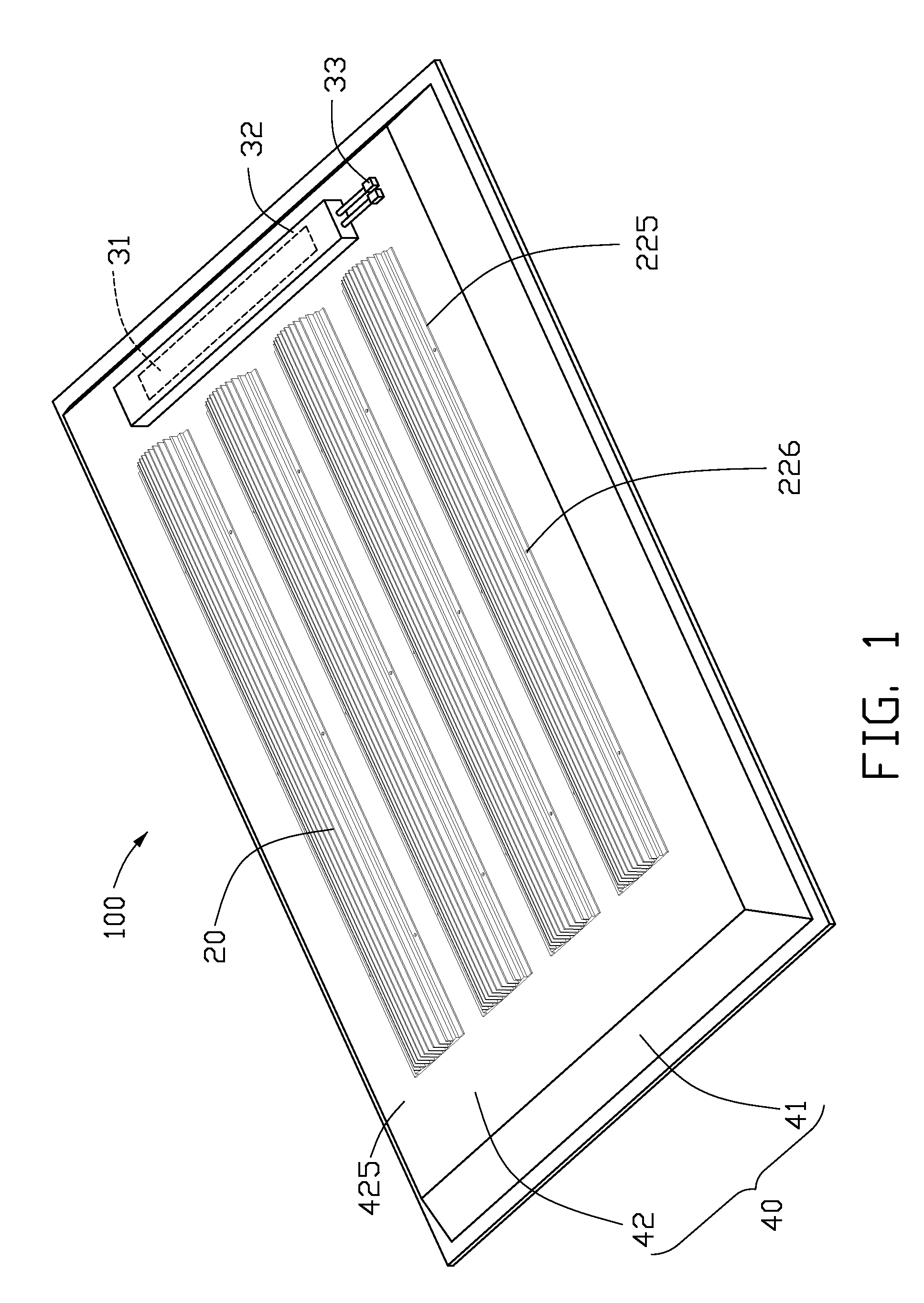
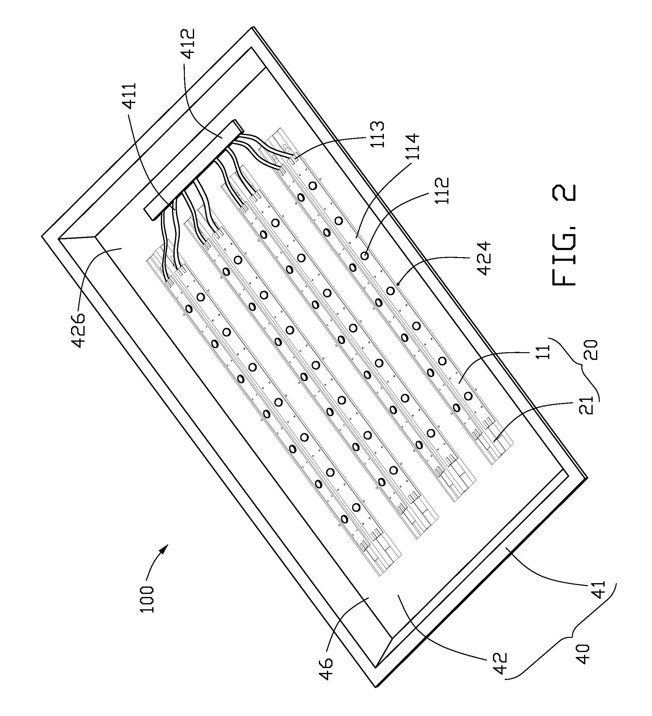
[0013]Referring to FIGS. 1 and 2, an LED illumination device 100 according to an exemplary embodiment includes a lampshade 40 and a plurality of light engines 20 mounted on the lampshade 40. The plurality of light engines 20 are identical to each other, and are arranged parallel to each other. Each light engine 20 includes a light source 11 and a heat dissipation member 21 for dissipating heat of the light source 11.

[0014]Referring to FIG. 3, the lampshade 40 has a configuration of a substantially truncated, hollow pyramid, and defines a room 46 therein for accommodating the light engines 20 including the light sources 11 therein. The lampshade 40 includes a side wall 41 and a mounting wall 42. The mounting wall 42 is substantially rectangular. The side wall 41 extends downwardly and slightly outwardly from a periphery of the mounting wall 42. The room 46 is surrounded by the side wall 41, and expands slightly from the mounting wall 42 along a downward direction. A plurality of elon...


PUM


Abstract

An LED illumination device includes a lampshade and a light engine arranged on the lampshade. The lampshade defines a room therein. The light engine includes a heat dissipation member, and a plurality of LEDs arranged on the heat dissipation member and received in the room of the lampshade. The heat dissipation member includes a heat pipe and a heat sink. The heat pipe forms a planar absorbing surface and a dissipating surface opposite to the absorbing surface. The absorbing surface of the heat pipe attaches to the LEDs to absorb heat therefrom. The heat sink includes a base attaching to the dissipating surface of the heat pipe to absorb heat of the heat pipe, and a plurality of fins extending from the base for dissipating heat absorbed from the heat pipe.

Description

BACKGROUND[0001]1. Technical Field[0002]The disclosure generally relates to LED illumination devices, and particularly to a light engine of an LED illumination device with high heat dissipating efficiency.[0003]2. Description of Related Art[0004]In recent years, LEDs are preferred for use in illumination devices rather than CCFLs (cold cathode fluorescent lamps) due to their excellent properties, including high brightness, long lifespan, wide color range, etc. For an LED, about eighty percents of the power consumed thereby is converted into heat. Therefore a heat dissipation device is necessary for timely and adequately removing the heat generated by the LED.[0005]Conventional heat dissipation devices, such as heat sinks, are usually made of copper, aluminum, or their alloy, and have a relatively high heat conductivity coefficient. The heat sink generally includes a base attached to the LED illumination device and a plurality of fins extending from the base for increasing a heat dis...

Claims


Application Information

Patent Timeline
Patent Type & Authority Patents(United States)
IPC IPC(8): F21V29/00
CPCF21V29/004F21V29/006F21V29/76F21V29/75F21S4/003F21V19/001H01L2924/0002F21Y2101/02H01L2924/00F21S4/20F21Y2115/10F21V29/51F21V29/74F21V29/745
Inventor LIU, TAY-JIAN
Owner HON HAI PRECISION IND CO LTD
Why Eureka
Try Eureka