Direct current motor

a direct current motor and direct current technology, applied in the direction of windings, magnetic circuit shapes/forms/construction, salient poles, etc., can solve the problems of large space occupation of commutator and direct current motor, large placement of circuit conductors, and large number of commutator short-circuit pieces, so as to reduce the size of space and reduce the size of short-circuit conductors

Inactive Publication Date: 2011-04-19
ASMO CO LTD
View PDF16 Cites 10 Cited by
  • Summary
  • Abstract
  • Description
  • Claims
  • Application Information

AI Technical Summary

Benefits of technology

[0004]An objective of the present invention is to provide a direct current motor that reduces the size of the short-circuit conductor (reduction in the size of a space for accommodating the short-circuit conductor).

Problems solved by technology

As a result, the space in which the short-circuit conductor is placed becomes large, making the commutator and the direct current motor large.
In addition, in the case where the short-circuit conductor is a great number of short-circuit pieces formed through punching out a conductor plate, the commutator having these short-circuit pieces becomes large.

Method used


Image

  • Direct current motor
  • Direct current motor
  • Direct current motor

Examples


first embodiment

[0038]FIGS. 1 to 9 show the present invention.

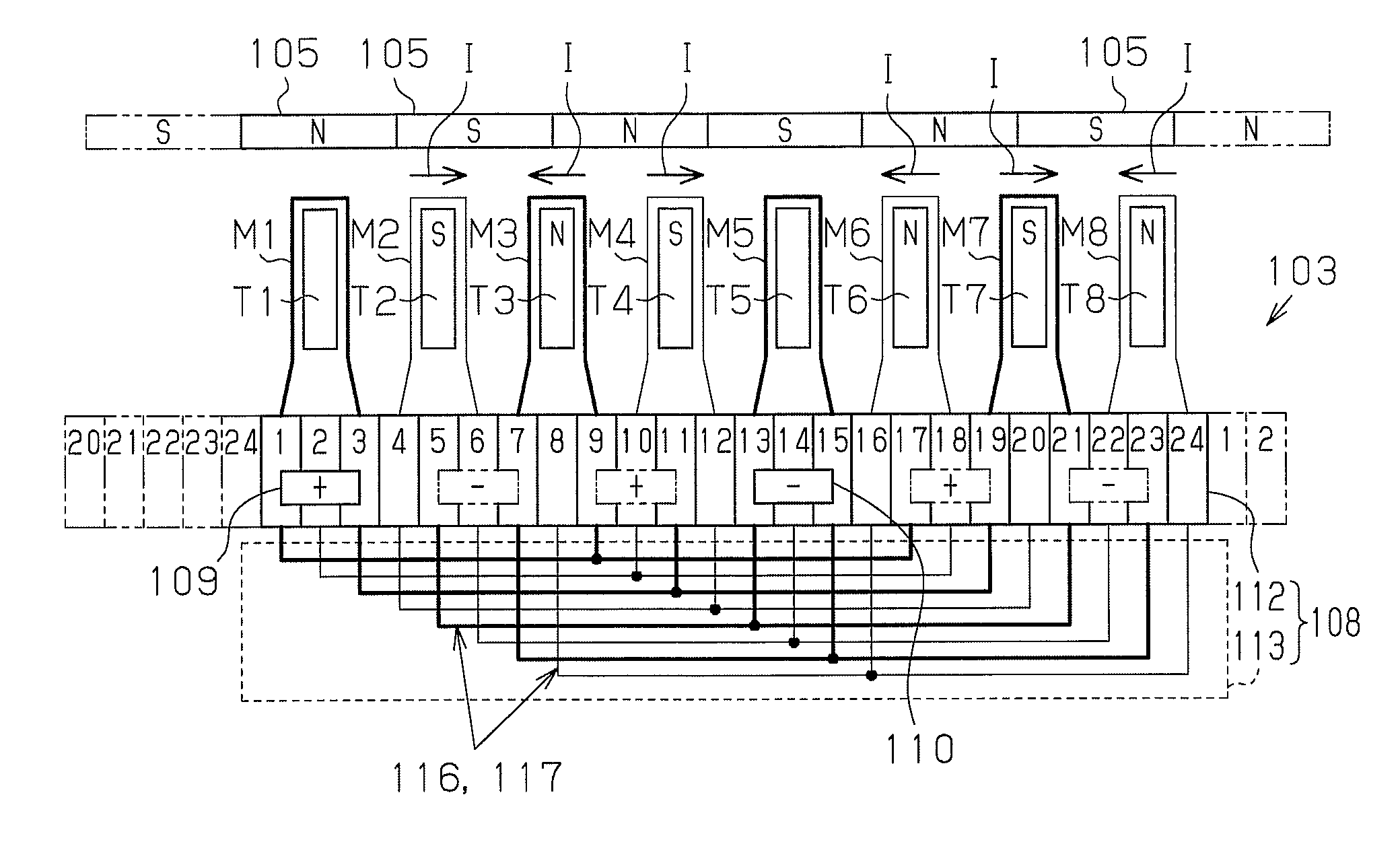
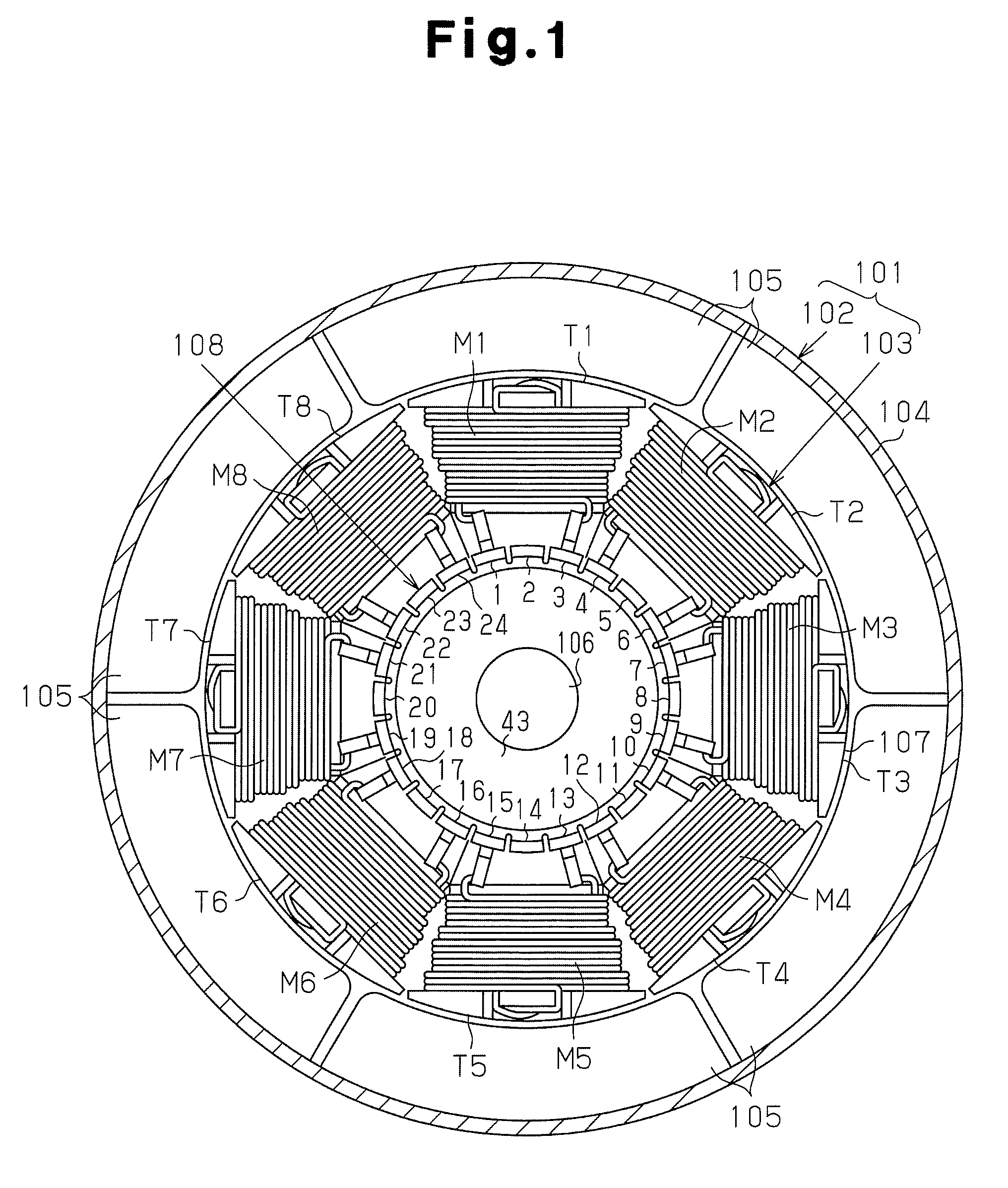
[0039]FIGS. 1 and 2 show a direct current motor 101 according to the first embodiment, and the direct current motor 101 is provided with a stator 102 and an armature 103. The stator 102 is provided with a cylindrical yoke housing 104 with a bottom and an end housing E for closing the opening of the yoke housing 104, and six magnets 105 are placed on the inner circumferential surface of the yoke housing 104. These magnets 105 are placed at an equal angular interval in the circumferential direction so as to form six magnetic poles in total.

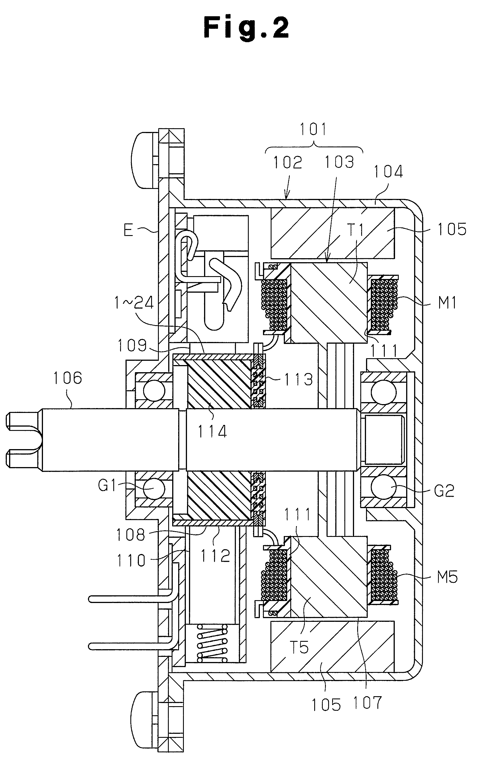
[0040]As shown in FIGS. 1 and 2, the armature 103, which is a rotor, is provided with a rotary shaft 106, and an armature core 107, and a commutator 108 which are respectively fixed to the rotary shaft 106. As shown in FIG. 2, the commutator 108 is located between the armature core 107 and the end housing E in the axial direction. The outer circumferential surface of the armature core 107 faces the magne...


PUM


Abstract

A stator has four or more magnetic poles. A commutator has a plurality of segments arranged in the circumferential direction and a short-circuit conductor for short-circuiting predetermined segments from among these segments. Each segment has an angular width WS, and there is a gap of an angular width WU between the segments. A substantial angular width WB of each of an anode brush and a cathode brush satisfies (n−1)(WS+WU)+WU<WB<n(WS+WU)+WU, where n is an integer no less than two. A plurality of coils are each connected to the corresponding one of the segments in order to form n closed loops. The closed loops each pass through the corresponding segments and are electrically independent of each other.

Description

BACKGROUND OF THE INVENTION[0001]The present invention relates to a direct current motor provided with a stator having four or more magnetic poles.[0002]The direct current motor disclosed in Japanese Laid-Open Patent Publication 2004-88915 has a stator where magnets are placed to form four or more magnetic poles. The rotary shaft rotates integrally with an armature core and a commutator core, and the armature core has a plurality of coils. The commutator has a plurality of segments arranged in the circumferential direction, and a short-circuit conductor for short-circuiting predetermined segments to each other. The coils are each connected to corresponding segments such that one closed circuit (closed loop) including the short-circuit conductor and all of the coils is formed between an anode brush and a cathode brush which contact and slide against the segments.[0003]In the direct current motor in the above described publication, however, the number of closed loops including the sho...

Claims


Application Information

Patent Timeline
Patent Type & Authority Patents(United States)
IPC IPC(8): H02K13/00H01R39/04H01R39/32
CPCH02K23/32
Inventor AOYAMA, TOMOHIROITO, YASUHIDEYAMAMOTO, TOSHIO
Owner ASMO CO LTD
Why Eureka
Try Eureka