Interactive labyrinth curve generation and applications thereof

a technology of interactive labyrinth and labyrinth, applied in the field of computer graphics and computer assisted design techniques, can solve the problems of large and complex maze and labyrinth patterns that are time-consuming and manual production, grids that are often stretched, and severe distortion of patterns, so as to reduce the number of strips and simplify assembly.

Active Publication Date: 2011-04-19
DAEDAL DOODLE
View PDF10 Cites 14 Cited by
  • Summary
  • Abstract
  • Description
  • Claims
  • Application Information

AI Technical Summary

Benefits of technology

[0009]In one aspect, the invention provides a computer-implemented method for generating a labyrinth. The method includes initializing curve evolution parameters and a curve network including a curve, evolving the curve using an iterative process such that during the iterative process the curve evolves in accordance with the curve evolution parameters and user input to produce an evolved curve having an increased geometric complexity (i.e., increasing curve length and number of inflection points), and rendering the evolved curve. Each iteration of the iterative process includes allowing the curve network and the curve evolution parameters to be modified by a user, resampling the curve to increase the uniformity of spacing between adjacent point samples of the curve, and spatially modulating the curve by the curve evolution parameters. The spatial modulation preferably includes computing, for each of the sample points, a displacement calculated by evaluating a function defined on the evolution space. The displacement preferably is a combination of a random displacement, a smoothing displacement, and an attraction-repulsion displacement.
[0011]The curve network may also include a boundary embedded in the evolution space and having a dimension one less than the evolution space dimension. Computing the attraction-repulsion displacement in this case includes computing a boundary displacement due to attraction-repulsion between the sample points of the curve and boundary sample points. In addition, the curve network may also contain a boundary gap corresponding to a subset of the boundary. Boundary gaps do not contribute to the calculation of displacements. Instead, the combination of boundary and boundary gaps allow the definition of a number of interconnected regions. A region is defined by a closed loop formed by connected boundary and boundary gaps. Each region may have its own unique set of curve evolution parameters that produce a distinct appearance of the evolving curves within that region. Although parameters can vary between regions, the same mathematical equations are used to evolve the curve network in all regions. The use of the same evolution equations allows blending of parameters where the evolving curves cross a boundary gap between two regions, thereby creating smooth transitions.
[0014]Preferably, evolving the curve includes rendering and displaying the curve during the evolution process. The evolution of the curve may be interactively controlled by allowing the curve network and the curve evolution parameters to be modified by a user. This modification may include, for example, allowing boundary sample points, boundary gap, curve sample points, and / or point evolution rates to be edited by the user. The editing of the curve evolution parameters may be implemented by allowing the user to select any region by clicking on it. Preferably, the selected region is rendered on the screen with a distinct appearance to make it clear in which area the parameter values are being modified. The user can then select from a finite list of predefined patterns. The parameter values for the selected pattern are then stored in the parameter functions within the region. Rather than editing all the parameters at once, the user can also choose to edit a single parameter within a selected region. The use of a simple, transparent user interface based on regions, boundary curves, and patterns eliminates the need for a user to understand the complex underlying mathematical parameters.
[0016]The developable surfaces generated by the method have several desirable properties that distinguish them from existing developable surface techniques:1. The geometry of the triangle strips has a visually attractive texture.2. The orientation, scale, and texture of the strips can be controlled by providing input functions in the form of images or texture maps. These controls can be used to create developable surface approximations with attractive stylized looks.3. The stylized appearance can be enhanced by rendering or manufacturing strips in different colors.4. The strips can approximate a three dimensional surface to a desired degree of accuracy by controlling the point spacing and strip width. The method is particularly well suited for smooth three dimensional surfaces.
[0017]5. The exact number of triangle strips (two or more) can be specified as an input parameter (i.e., the number of curve loops). In particular, the number of strips will typically be low (single digit) for most applications. In general, the lower the number of strips the simpler the assembly of the physical object.6. By evolving curve loops in semi-developable areas of a three dimensional surface, the number of self-intersections resulting from developing the triangle strips into the plane can be kept low.7. We note that the method produces attractive results even when the developed triangle strips self-intersect. Any intersecting strips are simply cut and manufactured in two pieces which are subsequently joined when the physical article is assembled.8. A simple heuristic rule on the placement of the input curves will reduce the number of self-intersections in the developed triangle strips.

Problems solved by technology

Due to their high geometric complexity, large and intricate maze and labyrinth patterns are time consuming to produce manually.
When projected to the surface of a 3D object, however, the grid often must be stretched, sometimes severely distorting the pattern.
The technique does not produce mazes or labyrinths.
The technique involves no evolution of a pattern toward increasing geometric complexity, and does not produce a maze or labyrinth.

Method used


Image

  • Interactive labyrinth curve generation and applications thereof
  • Interactive labyrinth curve generation and applications thereof
  • Interactive labyrinth curve generation and applications thereof

Examples


Embodiment Construction

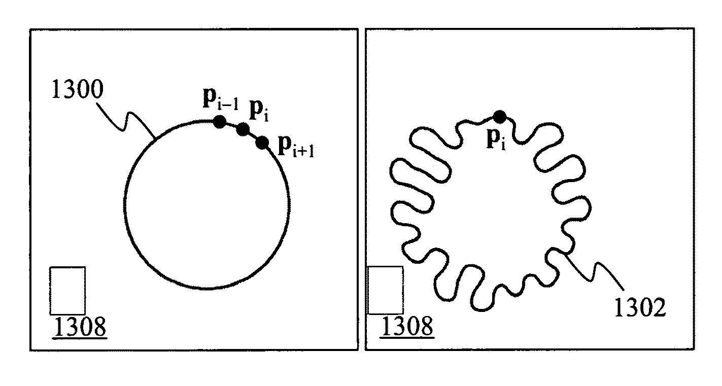
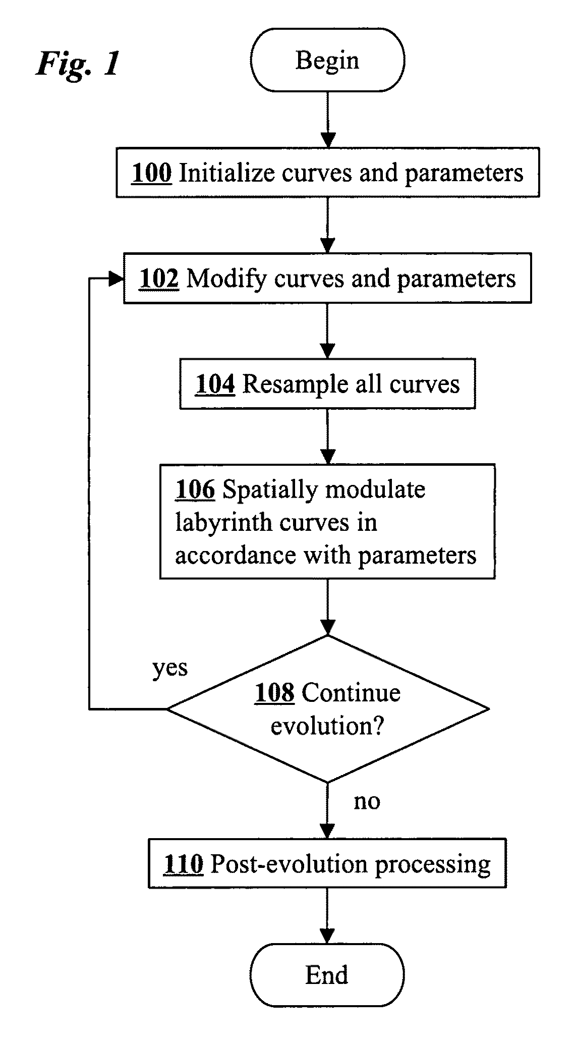
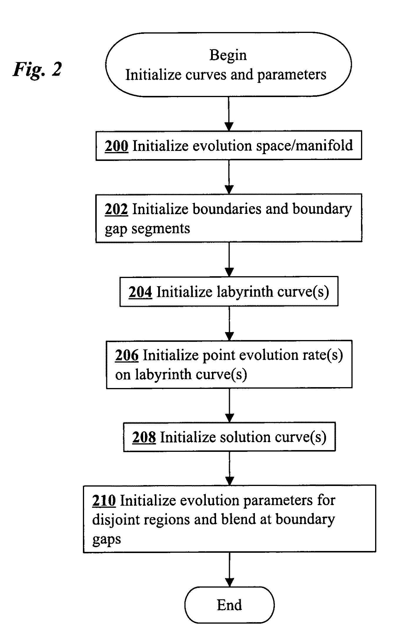
[0054]Main steps of a method for generating labyrinth curves according to an embodiment of the present invention are shown in FIG. 1. The method includes an initialization step 100 in which curve evolution parameters are initialized as well as a curve network including one or more curves. Each curve is evolved by iterating steps 102, 104, 106 as long as a decision is made at step 108 to continue the evolution. When the evolution is stopped, a post-evolution processing 110 is performed. Step 102 of the iterative process allows the curve network and evolution parameters to be modified by a user so that the evolution can be interactively guided as it progresses. In step 104 the curve is resampled to increase the uniformity of spacing between adjacent point samples of the curve, and in step 106 the curve is spatially modulated in accordance with the curve evolution parameters.

[0055]The effect of the iterative process shown in FIG. 1 is to evolve an initialized curve into an evolved curv...


PUM


Abstract

Complex labyrinth curves are interactively generated by an iterative process that spatially modulates curve evolution by an image or other function defined on the evolution space. After curves and evolution parameters are initialized [100], the iterative process allows the curve and evolution parameters to be interactively modified by a user [102], resamples the curves [104], and spatially modulates the curves according to the evolution parameters [106]. The evolved labyrinth curves are may be processed [110] for use in various applications including animation, maze creation, intricate artistic patterns, and graphical user interfaces that map linearly ordered data to the evolved curve and allow the data to be navigated using the rendered curve. The evolved curves can also be triangulated and projected to a plane to create patterns for manufacturing developable surfaces.

Description

FIELD OF THE INVENTION[0001]The present invention relates generally to computer graphics and computer assisted design techniques. More specifically, it relates to interactive computer-implemented methods for generating maze and labyrinth patterns.BACKGROUND OF THE INVENTION[0002]For centuries, maze and labyrinth patterns have been manually created as artistic designs, religious symbols, and intellectual puzzles. Due to their high geometric complexity, large and intricate maze and labyrinth patterns are time consuming to produce manually. Accordingly, various computer implemented methods have been developed to assist in the creation of such patterns.[0003]U.S. Pat. No. 6,347,995 describes the construction of a maze on a discrete rectangular grid. Two grid blocks are marked start and end by a user. The system then generates a random trunk path connecting start and end blocks. U.S. Pat. No. 4,718,017 presents similar techniques for generating mazes on a 2D grid of cells. The mazes are ...

Claims


Application Information

Patent Timeline
Patent Type & Authority Patents(United States)
IPC IPC(8): G06T11/20
CPCG06T11/001G06T11/40G06T11/203
Inventor PEDERSEN, HANS KOHLINGSINGH, KARANSHER
Owner DAEDAL DOODLE
Why Eureka
Try Eureka