
Structure for mounting batteries onto electric vehicles

a technology for electric vehicles and structures, applied in the direction of batteries/cells, propulsion by vehicles, tractors, etc., can solve the problems of shortening the range of electric vehicles and worsening drivability, so as to improve the crash-resistant capability of battery mounted, enhance the rigidity of electric vehicles, and prevent increased weight

Active Publication Date: 2011-04-26
MITSUBISHI MOTORS CORP
View PDF29 Cites 62 Cited by
  • Summary
  • Abstract
  • Description
  • Claims
  • Application Information

AI Technical Summary

Benefits of technology

The present invention aims to provide a structure for mounting a battery on an electric vehicle to improve its crash-resistant capability while preventing increased weight and enhancing the rigidity of the vehicle. The structure includes a metal body member, a resin battery case with a metal framework embedded in it, and a connecting member that connects the framework to the body member. This results in a battery mount that is both strong and lightweight.

Problems solved by technology

However, metal battery frames increase the weight of electric vehicles, and accordingly, the range of the electric vehicles becomes shorter and the drivability becomes worse.

Method used


Image

  • Structure for mounting batteries onto electric vehicles
  • Structure for mounting batteries onto electric vehicles
  • Structure for mounting batteries onto electric vehicles

Examples


Embodiment Construction

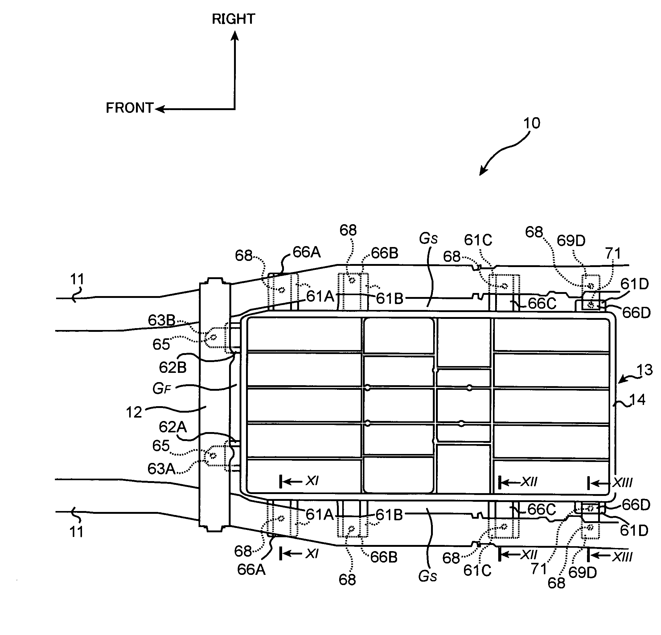
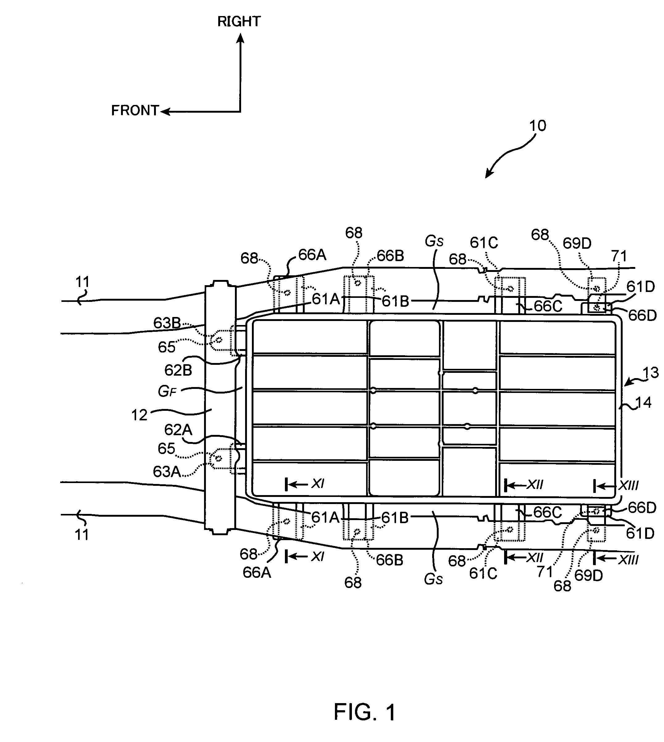
[0034]The embodiment of the present invention will now be described with reference to the accompanying drawings.

[0035]As shown in FIG. 1, side members (also called ‘body members’ or ‘first body members’) 11 and 11 are mounted on the left and right sides of an electric vehicle 10. The side members 11 and 11 extend in the longitudinal direction of the electric vehicle 10.

[0036]Further, a battery cross member (also called ‘body member’ or ‘second body member’) 12, which extends in the transversal direction (left-right direction) and which connects the pair of side members 11 and 11, is also mounted in the electric vehicle 10.

[0037]The side members 11 and 11 and the battery cross member 12 are iron, and constitute a body of the electric vehicle 10.

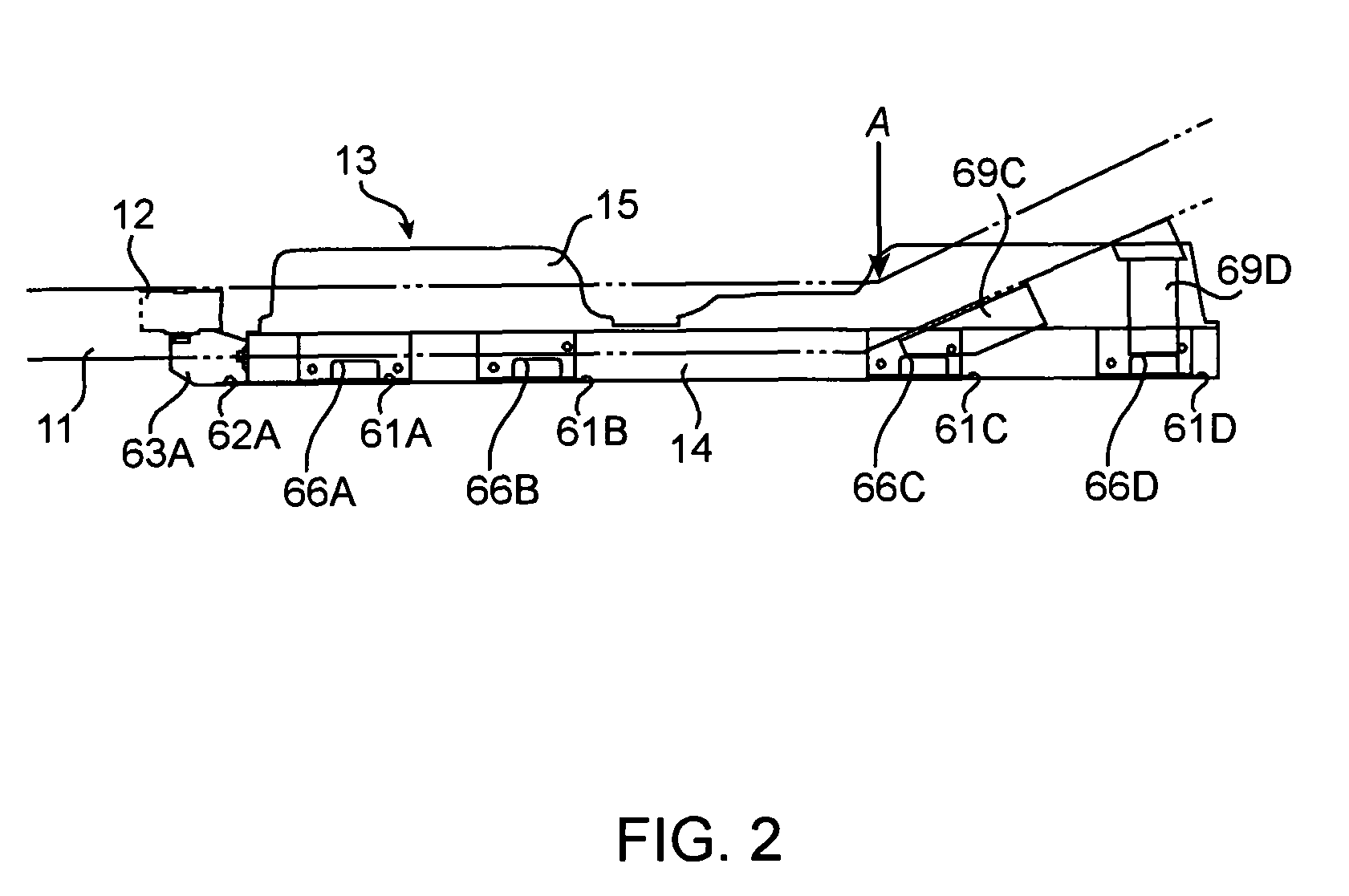
[0038]At a position between the pair of side members 11 and 11 and rear of the battery cross member 12, a battery case 13 is disposed. The battery case 13, which is made from polybutylene resin including glass fibers, contains and holds batter...


PUM


Abstract

A structure for mounting a battery onto an electric vehicle comprising: a body member, which is made from metal, forming a body of the electric vehicle a battery case, which is made from resin, containing the battery charging electric power for driving the electric vehicle; a framework member, which is made from metal, being embedded in the battery case; and a connecting member connecting between the framework member and the body member.

Description

BACKGROUND OF THE INVENTION[0001](1) Field of the Invention[0002]The present invention relates to a structure for mounting a battery onto an electric vehicle.[0003](2) Description of the Related Art[0004]Structures for mounting batteries using battery frames onto electric vehicles have been known in the art. The following related documents 1 and 2 disclose examples of such a structure. Although no description about material of the battery frame is disclosed in the related documents 1 and 2, conventional battery frames are metal because the battery frames support heavy batteries.[0005][Related Document 1] Japanese Laid-open Publication H7-69077[0006][Related Document 2] Japanese Laid-open Publication H7-69237[0007]However, metal battery frames increase the weight of electric vehicles, and accordingly, the range of the electric vehicles becomes shorter and the drivability becomes worse.SUMMARY OF THE INVENTION[0008]The present invention has been developed in consideration of this situ...

Claims


Application Information

Patent Timeline
Patent Type & Authority Patents(United States)
IPC IPC(8): B60R16/04B62J99/00
CPCB60K1/04B60R16/04B60K2001/0472B60L50/64Y02T10/70
Inventor SATO, KENICHINISHINO, HARUCHIKATAKASAKI, SEIICHI
Owner MITSUBISHI MOTORS CORP
Learn More