Sealed tubular joint comprising local and initial added thickness(es) by means of plastic expansion

a tubular joint and expansion technology, applied in the field of tubular joints, can solve the problems of insufficient sealing characteristics of threaded joints of this type, insufficient gas tightness of joints, and insufficient sealing characteristics of joints, so as to achieve high expansion rates and improve the effect of situation

Inactive Publication Date: 2011-04-26
VALLOUREC OIL & GAS FRANCE SAS
View PDF28 Cites 9 Cited by
  • Summary
  • Abstract
  • Description
  • Claims
  • Application Information

AI Technical Summary

Benefits of technology

[0012]One object of the invention is therefore to improve the situation, in particular in terms of sealing stability for...

Problems solved by technology

Furthermore, these joints must also in some cases be gas-tight.
However, a threaded joint of this type does not have sufficiently high sealing characteristics when the expansion rate is greater than 10%.
This joint w...

Method used


Image

  • Sealed tubular joint comprising local and initial added thickness(es) by means of plastic expansion
  • Sealed tubular joint comprising local and initial added thickness(es) by means of plastic expansion
  • Sealed tubular joint comprising local and initial added thickness(es) by means of plastic expansion

Examples


first embodiment

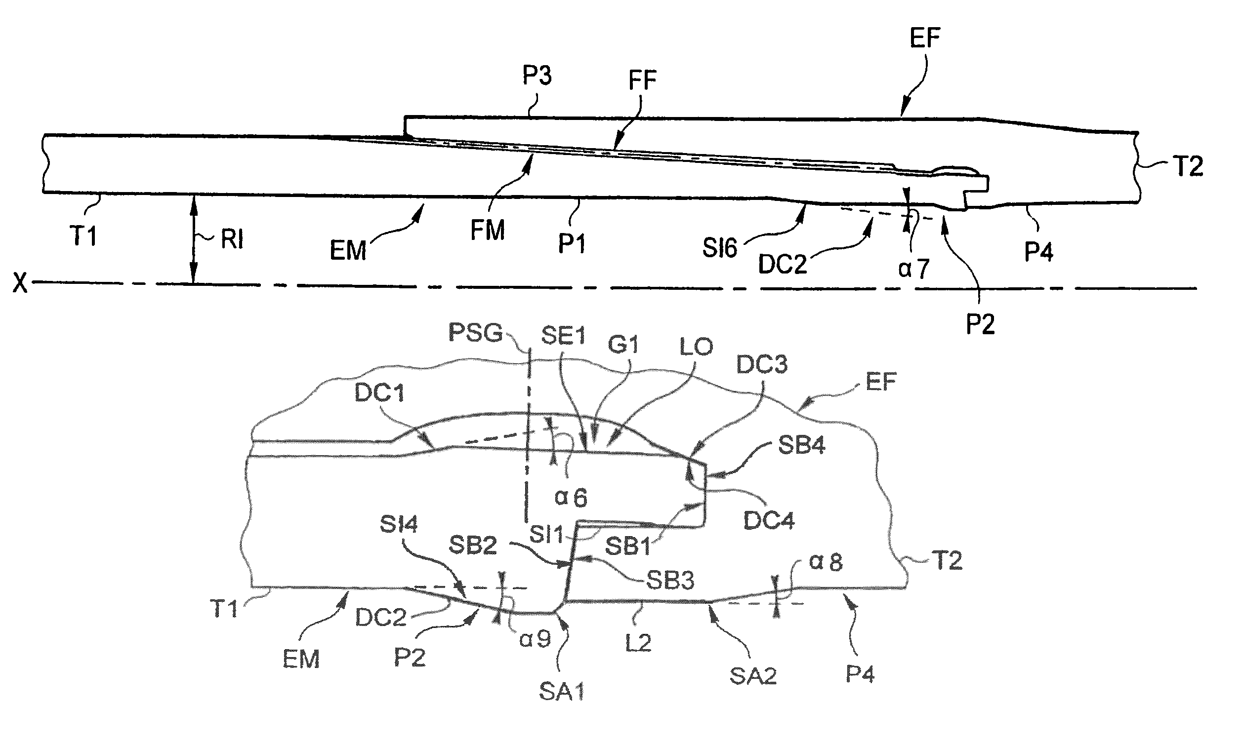
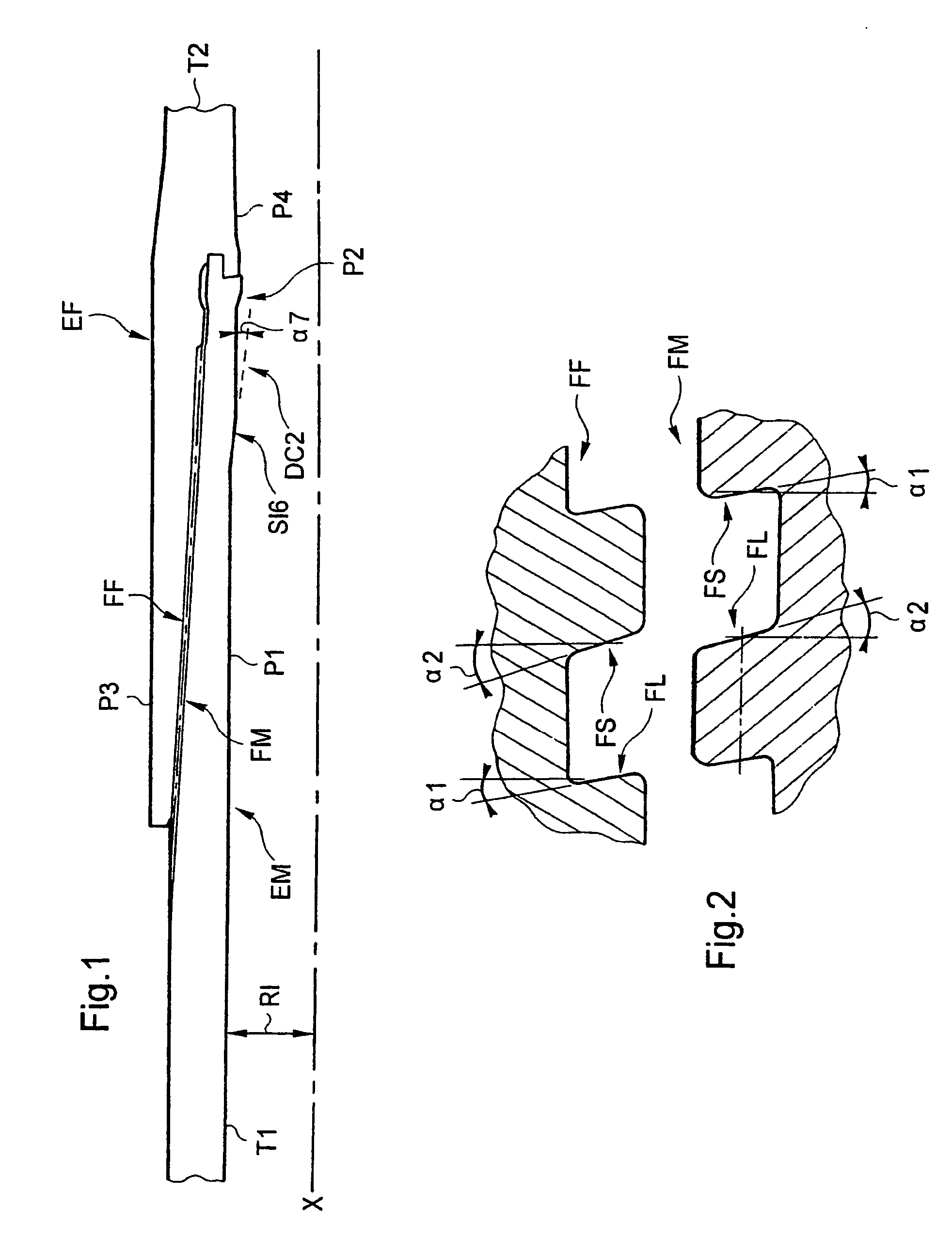
[0058]Reference will firstly be made to FIG. 1 to 8 in order to describe a tubular joint according to the invention. In this example, as is partially illustrated in FIG. 1, the joint allows the connection of two tubes T1 and T2, having an axis XX generated by revolution and being of great length i.e. several meters long, and more specifically of the male-type end EM (or male tubular element) of a first tube T1 and the female-type end EF (or female tubular element) of a second tube T2. In the illustrated embodiment, the tubes T1 and T2 have, for example, a common portion, the initial outer diameter of which is equal to approximately 193.68 mm (or 7⅝″). The common portion of a tube is the central portion remote from its two ends and having a substantially constant diameter.

[0059]As is illustrated in FIG. 1, the male end EM of a tube T1 comprises two portions P1 and P2. The first portion P1 extends the central portion of the tube T1 and is provided with an outer male thread FM, prefera...

second embodiment

[0120]The second abutment surface SB2 and the third abutment surface SB3 still initially have conical surfaces having substantially identical selected angles of inclination α4 relative to a plane perpendicular to the longitudinal direction A. However, in this second embodiment, the conical surfaces of the second abutment surface SB2 and third abutment surface SB3 are concave and convex respectively.

[0121]The inclinations of the angles α4 are selected such that the second abutment surface SB2 rests against the third abutment surface SB3, generating the first radial and sealing interference contact of the first outer surface SE1 (of the first lip L1) against the third inner surface SI3.

[0122]Preferably, as illustrated in FIG. 10 to 12, the second SB2 and third SB3 abutment surfaces have substantially the same initial inclination. This common inclination is preferably between an angle α4 of approximately +5° and an angle α4 of approximately +30°. More preferably still, it is equal to a...


PUM


Abstract

An expandable tubular joint including a male element with a male thread, a first annular lip having a first axially abutting surface, a first inner surface and a first outer surface, and a second abutting surface; and a female element with a female thread, a second annular lip having a third abutting surface, a second outer surface and a second inner surface, and a third inner surface and a fourth axially abutting surface which, together with the second outer surface, defines a first annular housing. The male tubular element includes a local added thickness at a fourth inner surface projecting out from the second abutting surface. After screwing, the first lip is housed in the annular housing and the abutting surfaces rest against one another, in order to enable the formation of an annular shoulder at the first outer surface during diametral expansion.

Description

BACKGROUND OF THE INVENTION[0001]1. Field of the Invention[0002]The invention relates to the field of tubular joints used, in particular, in wells, such as hydrocarbon wells and geothermal wells.[0003]2. Description of Related Art[0004]These joints are generally used to connect great length tubes together or to connect great length tubes and sleeves together, to allow casing or tubing strings to be formed.[0005]Moreover, these joints must be able to withstand considerable bending, tensile, compressive and sometimes torsional stresses, and also considerable pressure variations between the interior and the exterior. Furthermore, these joints must also in some cases be gas-tight. For these reasons, the joints are often of the threaded type and the sleeves and tubes are generally made from steel or from an alloy having a high yield point (possibly obtained by heat treatment). In the case of threaded joints, gas-tightness is most often provided by sealing surfaces with interfering “metal...

Claims


Application Information

Patent Timeline
IPC IPC(8): F16L13/14F16L15/00E21B43/10F16L15/04
CPCF16L15/004E21B43/106
Inventor DUBEDOUT, LAURENTDUQUESNE, BENOITVERGER, ERIC
Owner VALLOUREC OIL & GAS FRANCE SAS
Why Eureka
Try Eureka