
Vehicle door outer handle system

a technology for outer handles and vehicles, which is applied in the direction of computer control, carpet fasteners, program control, etc., can solve the problems of difficult to make thin operating handles, large space reserved within operating handles, etc., and achieves the effect of easy assembly, improved water resistance of circuit boards and electrodes, and easy integration of ground plates

Inactive Publication Date: 2011-04-26
HONDA LOCK MFG CO LTD
View PDF21 Cites 53 Cited by
  • Summary
  • Abstract
  • Description
  • Claims
  • Application Information

AI Technical Summary

Benefits of technology

[0008]In accordance with a third aspect of the present invention, in addition to the first or second aspect, among opposite faces of the circuit board, the electrodes are patterned on the face on the vehicle side. In accordance with the third aspect, it is possible to reliably detect the vehicle user's hand touching the face of the operating handle on the vehicle side when the vehicle user grasps the operating handle.
[0009]In accordance with a fourth aspect of the present invention, in addition to the first aspect, a sensor unit comprising the electrodes, the circuit board, and a covering portion made of a synthetic resin and covering the electrodes and the circuit board is fixedly housed in a housing recess formed in the handle main body so as to open on the cover side. In accordance with the fourth aspect, the circuit board on which the detection circuit is provided and the pair of electrodes can be easily assembled within the operating handle, and the water resistance of the circuit board and the electrodes can be improved.
[0010]In accordance with a fifth aspect of the present invention, in addition to the fourth aspect, the electrodes and the circuit board are mounted on a holder, a majority of the holder being covered by the covering portion so as to form a part of the sensor unit. In accordance with the fifth aspect, when the covering portion is die-molded so as to cover the electrodes and the circuit board, it is possible to position and support the electrodes and the circuit board with the holder, and thus easily die-mold the covering portion.
[0011]In accordance with a sixth aspect of the present invention, in addition to the fifth aspect, a ground plate forming a part of the sensor unit is mounted on the holder so as to cover the electrodes and is covered by the covering portion. In accordance with the sixth aspect, it is possible to easily incorporate the ground plate in the sensor unit, thereby enhancing the ease of assembly of the ground plate to the handle main body.
[0012]In accordance with a seventh aspect of the present invention, in addition to the fifth or sixth aspect, a portion of the holder projecting from the covering portion is mounted on a mounting seat provided on the handle main body. In accordance with the seventh aspect, since the holder is mounted at a predetermined position of the handle main body, it is possible to easily set the positions of the electrodes within the operating handle by mounting the electrodes on the holder.

Problems solved by technology

However, in this conventional arrangement, since electrodes formed as members that are separate from a circuit board are connected to a detection circuit provided on the circuit board, it is necessary to ensure that there is a space for arranging the electrodes within the operating handle in addition to a space for housing the circuit board, the space that has to be reserved within the operating handle is relatively large, and it is difficult to make a thin operating handle.

Method used


Image

  • Vehicle door outer handle system
  • Vehicle door outer handle system
  • Vehicle door outer handle system

Examples


Embodiment Construction

[0022]A mode for carrying out the present invention is explained below by reference to one embodiment of the present invention shown in the attached drawings.

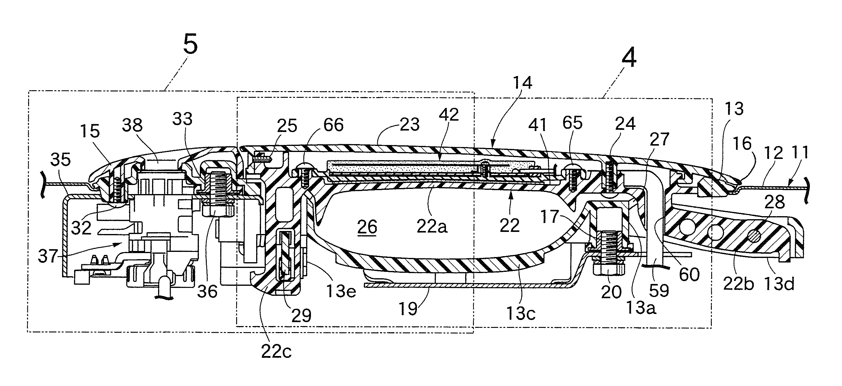
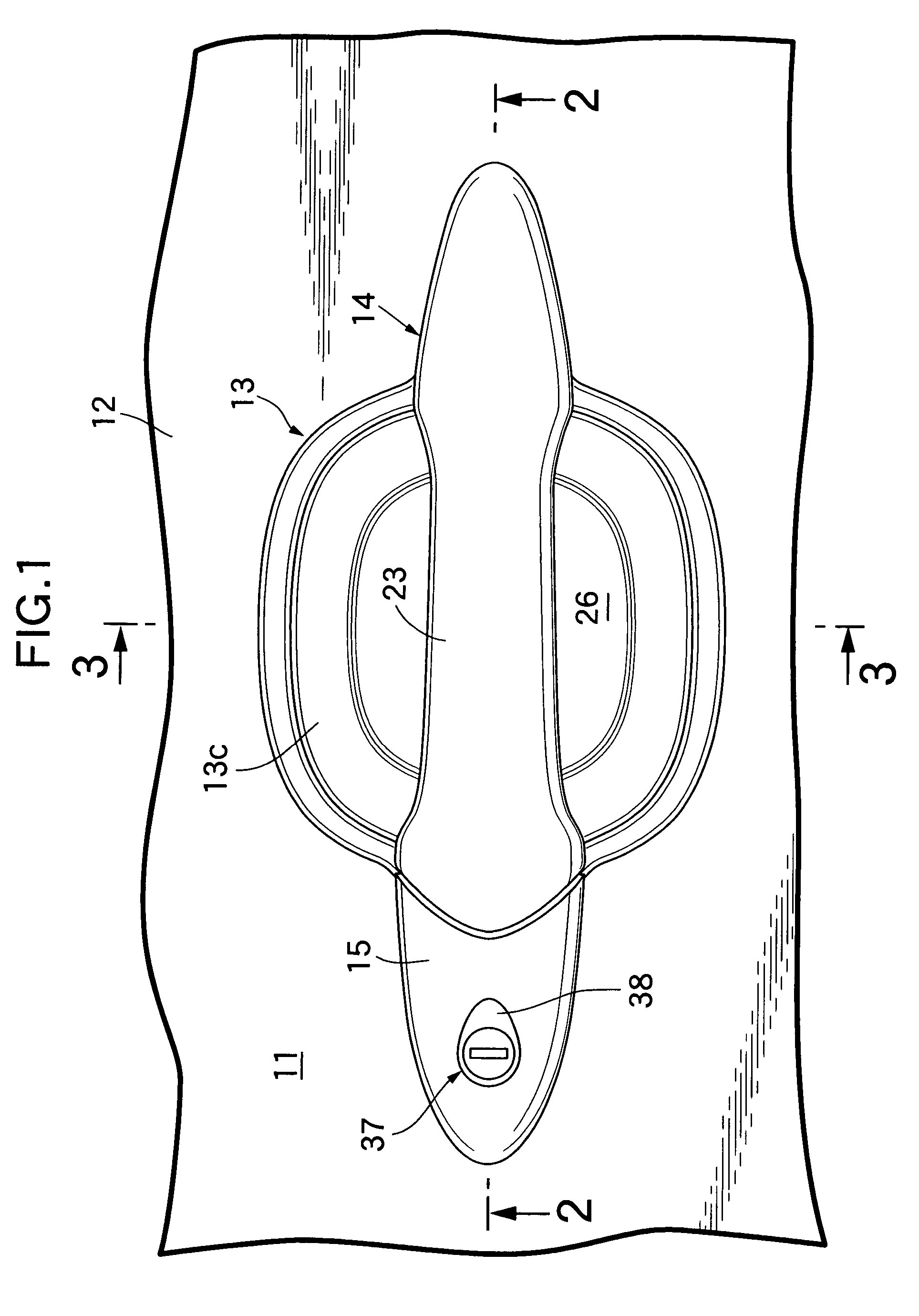
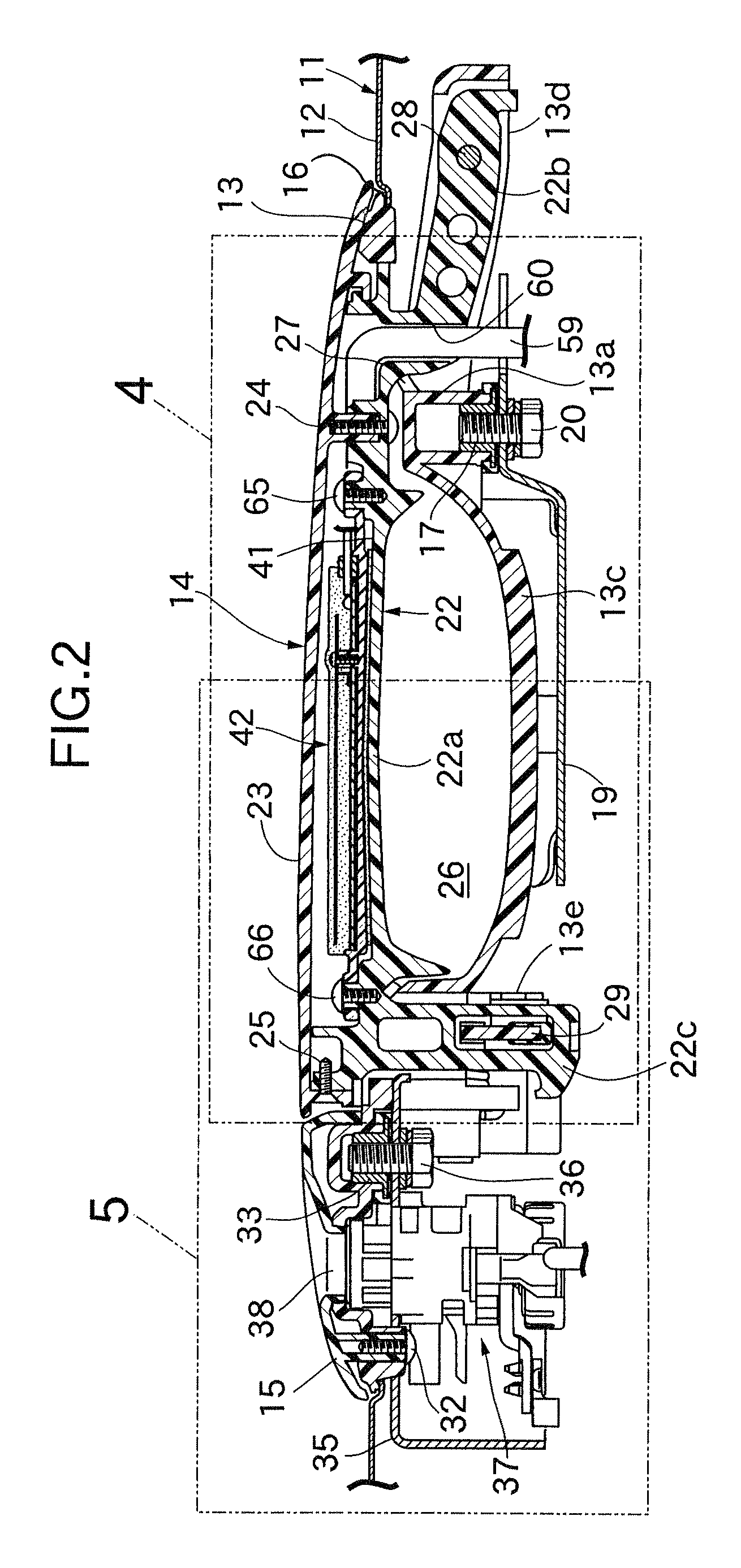
[0023]Referring firstly to FIG. 1 to FIG. 3, an outer panel 12 of a vehicle door 11, which is, for example, a side door of a passenger vehicle, is equipped with an outer handle system, and this outer handle system includes a handle case 13 mounted on the outer panel 12, an operating handle 14 extending in the fore-and-aft direction of the vehicle (the left and right direction in FIG. 1 and FIG. 2) and having one end, in the longitudinal direction, pivotably supported by the handle case 13, and a base member 15 mounted on the handle case 13 at the one end of the operating handle 14.

[0024]Referring in addition to FIG. 4 and FIG. 5, the outer panel 12 is provided with an aperture 16. A peripheral edge of the handle case 13, which is made of a synthetic resin so as to block the aperture 16, abuts against an outer face of the outer ...


PUM


Abstract

A vehicle door outer handle system is provided in which a pair of electrodes and a circuit board on which is provided a detection circuit for detecting a change in capacitance between the electrodes are housed within an operating handle formed from a handle main body and a cover covering the outer side of the handle main body, the operating handle being disposed on an outer side of a vehicle door, and the electrodes (43) being patterned on the circuit board (44), the operating handle thereby being made thin.

Description

CROSS-REFERENCE TO RELATED APPLICATION[0001]This application is a National Stage entry of International Application No. PCT / JP2004 / 008920, filed Jun. 18, 2004, the entire specification claims and drawings of which are incorporated herewith by reference.FIELD OF THE INVENTION[0002]The present invention relates to a vehicle door outer handle system that enables a vehicle user's intention to unlock to be confirmed by means of a change in capacitance when the vehicle user's hand approaches or touches an operating handle and, in particular, to a vehicle door outer handle system that includes an operating handle formed from a handle main body made of a synthetic resin and a cover made of a synthetic resin so as to cover the outer side of the handle main body, the operating handle being disposed on an outer side of a vehicle door and housing therewithin a pair of electrodes and a circuit board on which is provided a detection circuit for detecting a change in capacitance between the electr...

Claims


Application Information

Patent Timeline
Patent Type & Authority Patents(United States)
IPC IPC(8): E05B3/00H03K17/00B60J5/04B60R25/24E05B1/00E05B65/20G07C9/00
CPCB60R25/246E05B81/78G07C9/00309G07C2209/65G07C2009/00793Y10S292/65Y10T292/0908Y10T292/57H03K17/962
Inventor NITAWAKI, MASAKATSUFUJIWARA, HIROTOHIDAKA, OSAMUOTSUTA, YUHOSUEYOSHI, MASAHIKO
Owner HONDA LOCK MFG CO LTD
Learn More