Eureka AIR delivers breakthrough ideas for toughest innovation challenges, trusted by R&D personnel around the world.

Surgical retractor

a retractor and surgical technology, applied in the field of retractors, can solve the problems of inability to properly assemble and move parts in undesired positions, and it takes a certain amount of effort and skill to achieve the effect of simple procedur

Inactive Publication Date: 2011-04-26
MCCARTHY PATRICK M +1
View PDF8 Cites 18 Cited by
  • Summary
  • Abstract
  • Description
  • Claims
  • Application Information

AI Technical Summary

Benefits of technology

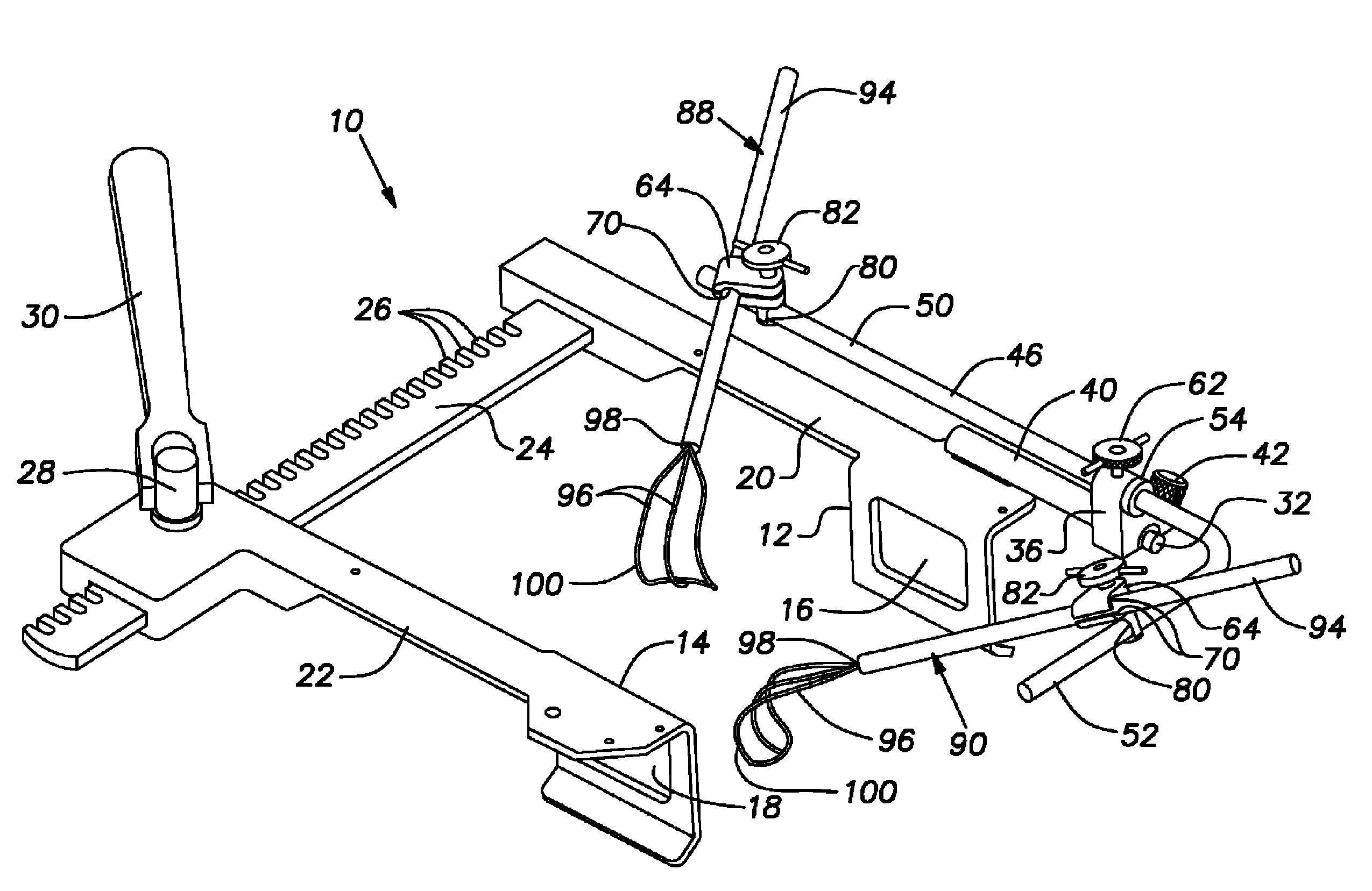
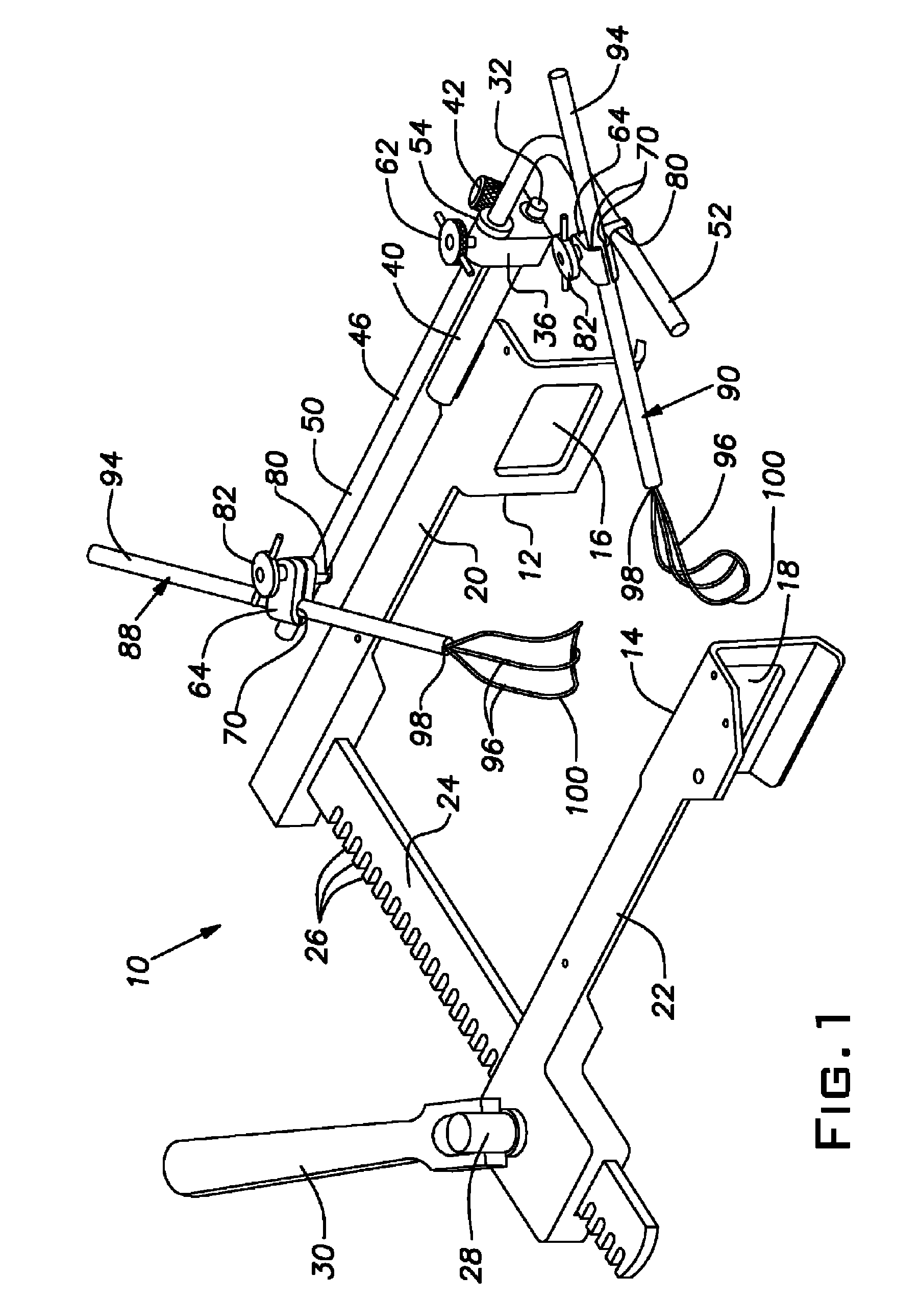
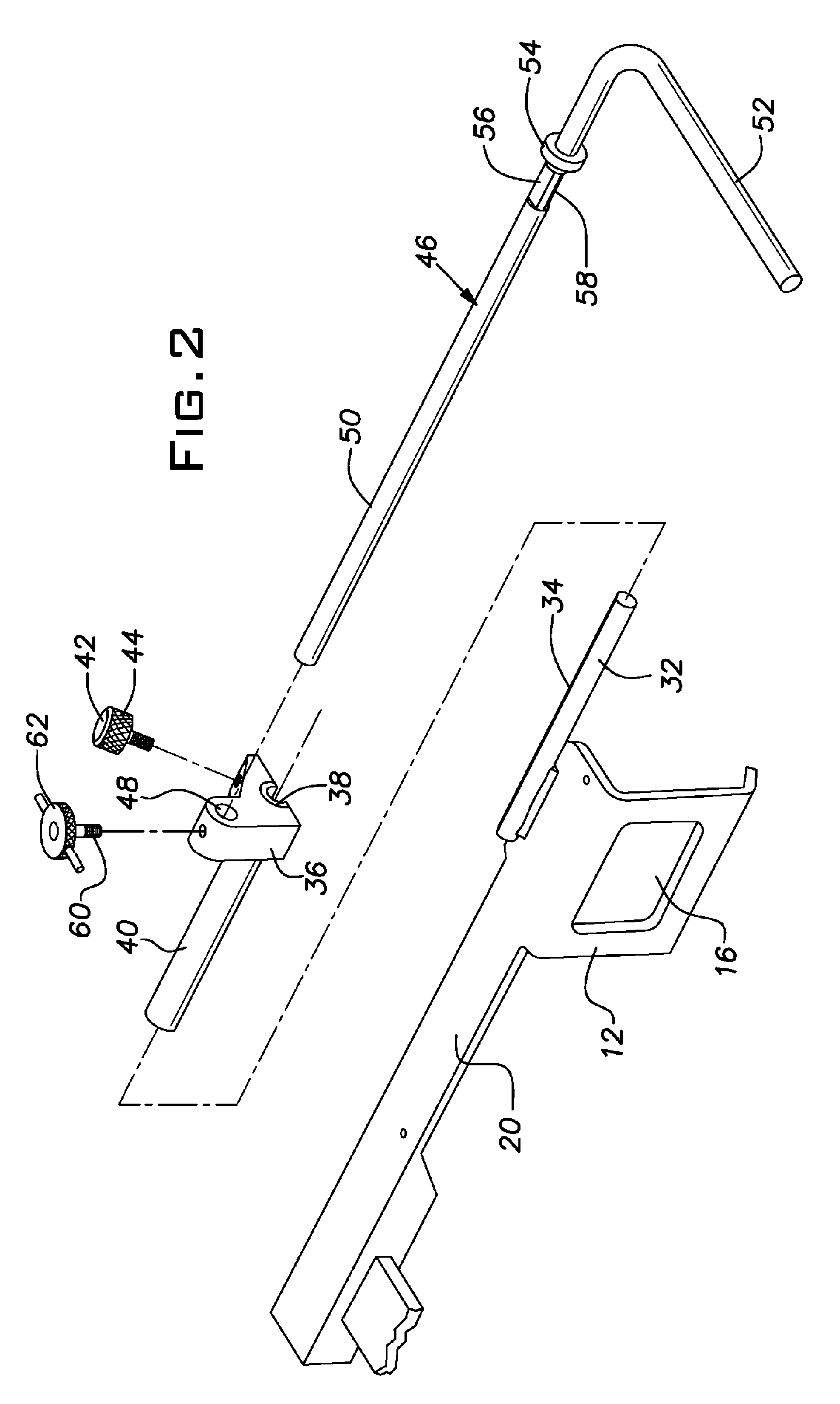
[0011]A first rod is connected to the bar on a selected arm by means of a first bracket. Optionally, a second rod is connected to the bar on the other arm by means of a second bracket. The brackets carry first set screws that enable the brackets to be locked in position relative to their respective bars. The brackets are slidable along the bars in order to permit the longitudinal position of the rods relative to the arms to be adjusted. The brackets are large enough that the rods are disposed above the arms a desired distance. Each bar includes a longitudinally extending flat surface. The first set screw engages the flat surface so as to locate the bracket and its associated rod in a precise rotational position relative to the bar. The interaction of the first set screw and the flat surface also prevents the relative position of the components from being changed under forces that may be applied during the course of a surgical procedure.
[0012]In the preferred embodiment, the first rod is L-shaped, while the second rod is straight. Each of the rods extends through an opening in its associated bracket and is retained in place there by a second set screw. Each rod preferably includes a circumferentially extending shoulder on the part that extends through the opening in the bracket. The shoulder enables the rod to be positioned exactly as desired relative to the arm to which it is connected. Preferably a flat surface is formed on the rod adjacent the shoulder for engagement by the second set screw. The flat surface causes the rod to be positioned precisely as necessary to perform a surgical procedure. In the particular case of the L-shaped rod, a second flat surface can be provided that is spaced circumferentially from the first flat surface. The second flat surface enables the L-shaped rod to be moved to an out-of-the way position and locked in place there.
[0013]The rods enable one or more small retractor blades of the wire basket type having elongate handles to be used to retract portions of the heart. Each retractor blade is connected to one of the rods by means of a universal clamp that grasps both the handle of the blade and the rod. Each clamp includes a nut that enables the clamp to be tightened or loosened with one hand. The clamps permit the blades to be moved to any position that may be desired by the surgeon. The basket portions of the retractor blades are made of a malleable wire that enables the configuration of the blades to be changed by the surgeon as desired.
[0014]As will be appreciated from the foregoing description, the cardiovascular retractor according to the invention can be attached to the thoracic retractor according to the invention in a very simple procedure that will enable the surgeon to position the components exactly as desired without guesswork or judgment being required. The components of the cardiovascular retractor will retain their initial position under all operative conditions until movement to another position is desired. In addition, the basket portions of the retractor blades according to the invention are adjustable in order to accommodate the anatomy of different patients.

Problems solved by technology

While the cardiovascular retractors disclosed in the '150 and the '468 patents are effective, it takes a certain amount of effort and skill in order to assemble them properly.
After assembly, certain components inadvertently can be moved into undesired positions under the forces that are placed on the retractor during the course of performing a surgical procedure.

Method used


Image

  • Surgical retractor
  • Surgical retractor
  • Surgical retractor

Examples


Embodiment Construction

[0021]Referring generally to FIGS. 1-5, a surgical retractor according to the invention is indicated generally by the reference numeral 10. The retractor 10 includes a pair of small, generally rectangular parallel grips 12, 14. The grips 12, 14 have rectangular openings 16, 18 formed therein, respectively. The grips 12, 14 are mounted at the ends of arms 20, 22, respectively.

[0022]The arms 20, 22 extend at right angles away from a crossbar 24 having a plurality of spaced teeth 26. The arm 20 is fixed to the crossbar 24, while the arm 22 is movable along the crossbar 24 so as to move the grip 14 toward or away from the grip 12. Movement of the arm 22 is accomplished by a pinion 28 that engages the teeth 26 of the crossbar 24. A handle 30 is connected to the pinion 28 for purposes of rotating the pinion 28.

[0023]A generally cylindrical bar 32 is mounted to the upper surface of one or both of the arms 20, 22. For convenience, only one bar 32 will be discussed herein, and such discussio...


PUM


Abstract

A surgical retractor includes a pair of parallel arms that are mounted to a toothed crossbar. One of the arms is fixed to one end of the crossbar, while the other arm is movable along the crossbar by means of a pinion. One or both of the arms includes on its upper surface a bar having a longitudinally extending flat surface. A rod is connected to the bar by means of a bracket. The bracket can be locked in position relative to the bar by a first set screw that engages the flat surface. A rod extends through an opening in the bracket and is retained in place there by a second set screw. The rod includes a circumferentially extending shoulder that engages the bracket so as to locate the rod in a desired position. One or more flat surfaces are formed on the rod adjacent the shoulder for engagement by the second set screw. One of the flat surfaces causes the rod to be positioned precisely as necessary to perform a surgical procedure, while the other of the flat surfaces enables the rod to be moved to an out-of-the way position and locked in place there. One or more retractor blades of the wire basket type are connected to the rod by means of universal clamps. The basket portions of the retractor blades are made of a malleable wire that enables the configuration of the blades to be changed by the surgeon as desired.

Description

CROSS-REFERENCE TO RELATED APPLICATION[0001]This application claims priority to U.S. provisional patent application No. 60 / 607,475, entitled SURGICAL RETRACTOR, filed Sep. 3, 2004.BACKGROUND OF THE INVENTION[0002]1. Field of the Invention[0003]The invention relates to retractors that are used in various types of surgeries such as cardiovascular surgery and, more particularly, to a retractor that can be conveniently assembled and adjusted by the surgeon.[0004]2. Description of the Prior Art[0005]In the course of such operative procedures as mitral valve surgery or mammary artery surgery, it is necessary to expose the heart. Such exposure has been accomplished by performing either a full or partial sternotomy (cutting an incision through the sternum and retracting the sternum) or by cutting an incision between adjacent ribs. The retraction is accomplished by a thoracic retractor that employs parallel grips that engage the edges of the incision. The grips are mounted perpendicularly to...

Claims


Application Information

Patent Timeline
Patent Type & Authority Patents(United States)
IPC IPC(8): A61B1/32
CPCA61B17/0206A61B17/0293
Inventor MCCARTHY, PATRICK M.SANTILLI, ALBERT N.
Owner MCCARTHY PATRICK M
Why Eureka
Eureka Blog
Learn More