Electronic control system for dust blowing and sucking equipment rotary frame

An electronic control system and equipment technology, applied in general control systems, control/regulation systems, electrical program control, etc., can solve the problems of scratches on the surface and unsatisfactory effect of steel pipe dust removal.

Inactive Publication Date: 2016-02-17
TIANJIN SERI MACHINERY EQUIP
View PDF0 Cites 2 Cited by
  • Summary
  • Abstract
  • Description
  • Claims
  • Application Information

AI Technical Summary

Problems solved by technology

[0003] The technical problem to be solved by the present invention is to provide an electric control system for the turret of the soot blowing and suction equipment with precise rotation positioning, high degree of automation, and a simple operating system, aiming at solving the dust removal effect of the existing steel pipe after the soot blowing and suction process Unsatisfactory, scratches on the surface

Method used


Image

  • Electronic control system for dust blowing and sucking equipment rotary frame

Examples


Embodiment Construction

[0015] In order to further understand the invention content, characteristics and effects of the present invention, the following examples are given, and detailed descriptions are as follows in conjunction with the accompanying drawings:

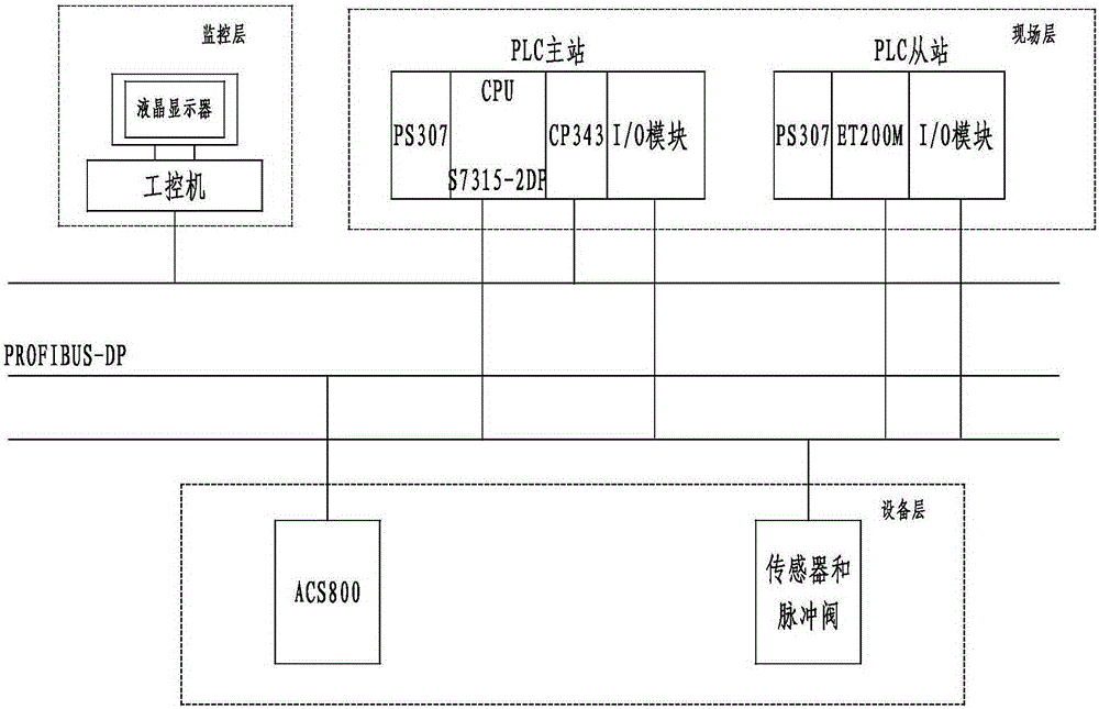
[0016] see figure 1 , an electric control system for a soot blowing and suction equipment turret, at least including:

[0017] Equipment layer; the equipment layer includes a speed sensor for collecting the rotation speed of the turret, a frequency converter for controlling the rotation of the turret, and an absolute encoder is installed on the frequency converter;

[0018] On-site layer; the on-site layer includes Siemens S7300 series PLC; the Siemens S7300 series PLC includes two parts, PLC master station and PLC slave station; wherein: the PLC master station includes S7315-2DP controller, CP343-1 Ethernet communication module; And master station I / O module; Described PLC slave station comprises Siemens ET200M and slave station I / O module;...


PUM


Abstract

The invention discloses an electronic control system for a dust blowing and sucking equipment rotary frame. The electronic control system comprises an equipment layer, a field layer and a monitoring layer. The equipment layer comprises a speed sensor and a frequency converter, and the frequency converter is provided with an absolute value encoder. The field layer comprises a PLC. The PLC comprises a PLC master station and a PLC slave station. The PLC master station comprises an S7 315-2DP controller, a CP343-1 Ethernet communication module and a master station I / O module. The PLC slave station comprises a siemens ET200M and a slave station I / O module. The monitoring layer comprises an industrial personal computer and a touch screen. The industrial personal computer is connected with the touch screen through a data line and carries out data exchange with the CP343-1 Ethernet communication module through an industrial Ethernet. The frequency converter is connected with the S7 315-2DP controller and the siemens ET200M through a profibus. The speed sensor is connected with the master station I / O module and the slave station I / O module through shielding cables.

Description

technical field [0001] The invention relates to a soot blowing and suction equipment for steel pipes, more specifically, an electric control system for a turret of the soot blowing and suction equipment. Background technique [0002] The function of the soot blowing and suction equipment is to remove the iron scale of the steel pipe to meet the requirements of flaw detection, and is equipped with dust removal equipment to meet the requirements of environmental protection. With the increase in the number of equipment put into production, the in-depth design and repeated inspections in practice, it was found that the old soot blowing and suction equipment had the following defects: 1. Because the traditional technology uses a mechanical transmission mechanism to drive the turret to rotate, the proximity switch is used for positioning, and the rotation positioning The precision is low, the air blowing hole is inconsistent with the center of the steel pipe, and the dust removal ...

Claims


Application Information

Patent Timeline
Patent Type & Authority Applications(China)
IPC IPC(8): G05B19/418G01N1/34
CPCY02P90/02G05B19/4186G01N1/34
Inventor 丁先进陈春梅
Owner TIANJIN SERI MACHINERY EQUIP
Why Eureka
Try Eureka