Brushless motor rotation-position detection system
a technology of rotation position and brushless motor, which is applied in the direction of motor/generator/converter stopper, electronic commutator, dynamo-electric converter control, etc., can solve the problems of not being able to accurately detect the system is expensive, so as to achieve accurate detection of the rotation position of a brushless motor, simple and inexpensive
- Summary
- Abstract
- Description
- Claims
- Application Information
AI Technical Summary
Benefits of technology
Problems solved by technology
Method used
Image
Examples
embodiment 1
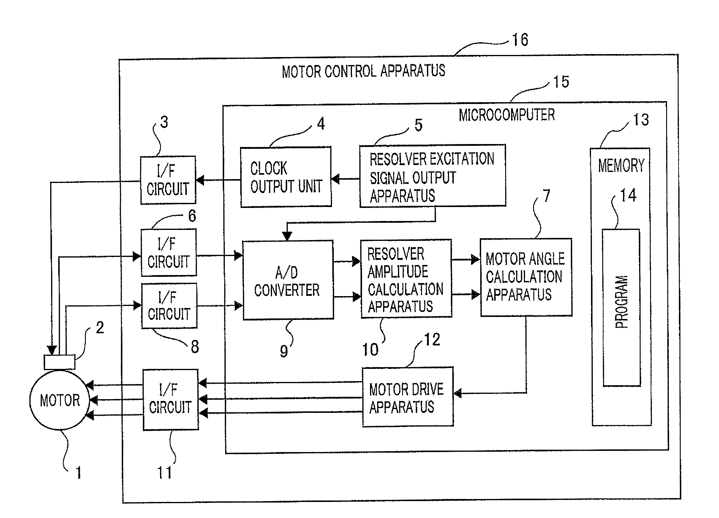
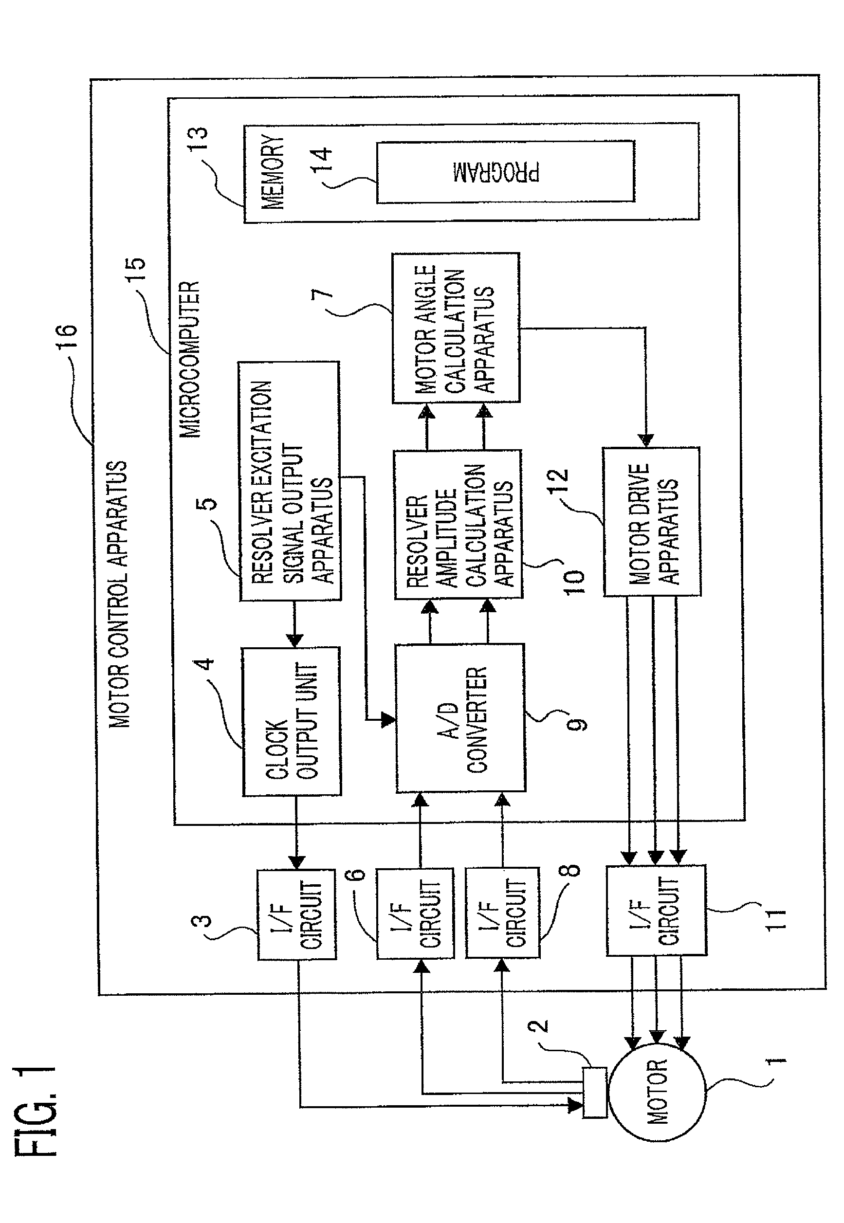
[0028]FIG. 1 is a system configuration diagram of a brushless motor rotation-position detection system according to Embodiment 1 of the present invention. In FIG. 1, a brushless motor rotation-position detection system according to Embodiment 1 is provided with a motor controller 16 for driving a brushless motor 1 and a resolver 2 for detecting the motor position of the brushless motor 1, which is a control subject. The motor controller 16 is provided with an interface circuit 3 (referred to only as an I / F circuit, hereinafter) for exciting the resolver 2, an I / F circuit 6 for receiving a sine wave signal outputted by the resolver 2, an I / F circuit 8 for receiving a cosine wave signal outputted by the resolver 2, an I / F circuit 11 for driving the brushless motor 1, and a microcomputer (referred to also as a calculation means, hereinafter) 15 that performs calculation for controlling the motor, based on rotation-position information on the brushless motor 1.
[0029]The microcomputer 15...
embodiment 2
[0036]Next, there will be explained Embodiment 2 of the present invention with reference to FIGS. 5 through 8. The configuration diagram of the system according to Embodiment 2 is the same as that of the system according to Embodiment 1.
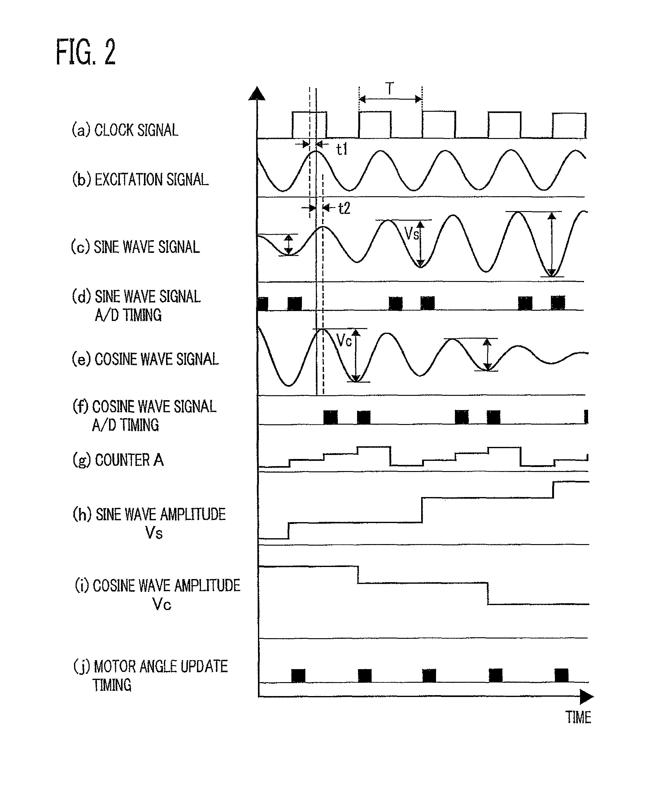
[0037]At first, in a time that is half of the excitation period T for the resolver, the processing represented in FIG. 6 is called up. In FIG. 6, it is determined in the step S801 whether or not the present timing is a reference-voltage learning timing. In Embodiment 2, unlike Embodiment 1, each of the sine wave signal and the cosine wave signal is A / D-converted only at one side timing (only when the excitation signal is the maximum value or the minimum value), as represented in (d) and (f) of FIG. 5. Accordingly, for the purpose of obtaining the sine wave amplitude and the cosine wave amplitude, it is required that the calculations expressed by Equations (6) and (7) are performed by utilizing the respective A / D-converted values and a reference volta...
embodiment 3
[0045]Next, there will be explained Embodiment 3 of the present invention with reference to FIG. 9. Embodiment 3 differs from Embodiment 2 in terms of reference-voltage learning processing; however, because the other processing is similar to that in Embodiment 2, only the reference-voltage learning processing will be explained.
[0046]At first, as is the case with Embodiment 2, in the case where it is determined in the step S801 that the present timing is the reference-voltage learning timing, the step S801 is followed by the step S1101. In the step S1101, excitation of the resolver is interrupted. When the excitation of the resolver is interrupted, each of the sine wave signal and the cosine wave signal becomes equal to the reference voltage. Accordingly, in the step S1102, A / D conversion is applied to the terminal to which the sine wave signal is inputted, and in the step S1103, the value obtained through the conversion is stored in a memory, as a sine wave reference voltage Vscen2....
PUM
 Abstract
Description
Claims
Application Information
 - R&D
- Intellectual Property
- Life Sciences
- Materials
- Tech Scout
- Unparalleled Data Quality
- Higher Quality Content
- 60% Fewer Hallucinations
Browse by: Latest US Patents, China's latest patents, Technical Efficacy Thesaurus, Application Domain, Technology Topic, Popular Technical Reports.
© 2025 PatSnap. All rights reserved.Legal|Privacy policy|Modern Slavery Act Transparency Statement|Sitemap|About US| Contact US: help@patsnap.com


