Brushless motor rotation-position detection system

a technology of rotation position and brushless motor, which is applied in the direction of motor/generator/converter stopper, dynamo-electric converter control, instruments, etc., can solve the problems of not being able to accurately detect the system is expensive, so as to achieve accurate detection of the rotation position of a brushless motor, simple and inexpensive

Active Publication Date: 2011-10-20
MITSUBISHI ELECTRIC CORP
View PDF5 Cites 2 Cited by
  • Summary
  • Abstract
  • Description
  • Claims
  • Application Information

AI Technical Summary

Benefits of technology

[0010]The present invention has been implemented in order to solve the foregoing conventional problems from above point of view; the objective thereof is to provide a brushless motor rotation-position detection system in which only a single A / D converter is mounted, in which no sample / hold circuit is provided in a microcomputer or an external peripheral circuit thereof, and that can accurately detect the rotation position of a brushless motor although simply and inexpensively configured.
[0013]In the brushless motor rotation-position detection system according to the present invention, the microcomputer thereof is provided with only a single A / D converter, and the rotation position of the brushless motor can accurately be detected through a simple and inexpensive configuration, even when no sample / hold circuit is provided.

Problems solved by technology

As described above, for the purpose of accurately detecting the rotation position of a brushless motor, it is required to mount a plurality of A / D converters or a sample / hold circuit on the rotation-position detection system; thus, there has been a problem that the system is expensive.
However, in the case of the steering system described in Japanese Patent No. 2959044, because the transfer mechanism for rotating an outboard engine and the steering system are mechanically separated, the torque of a brushless motor is not sensed by a steerer; thus, the rotation position of a brushless motor is not required to be as accurate as that of Japanese Patent No. 3427876.

Method used


Image

  • Brushless motor rotation-position detection system
  • Brushless motor rotation-position detection system
  • Brushless motor rotation-position detection system

Examples


embodiment 1

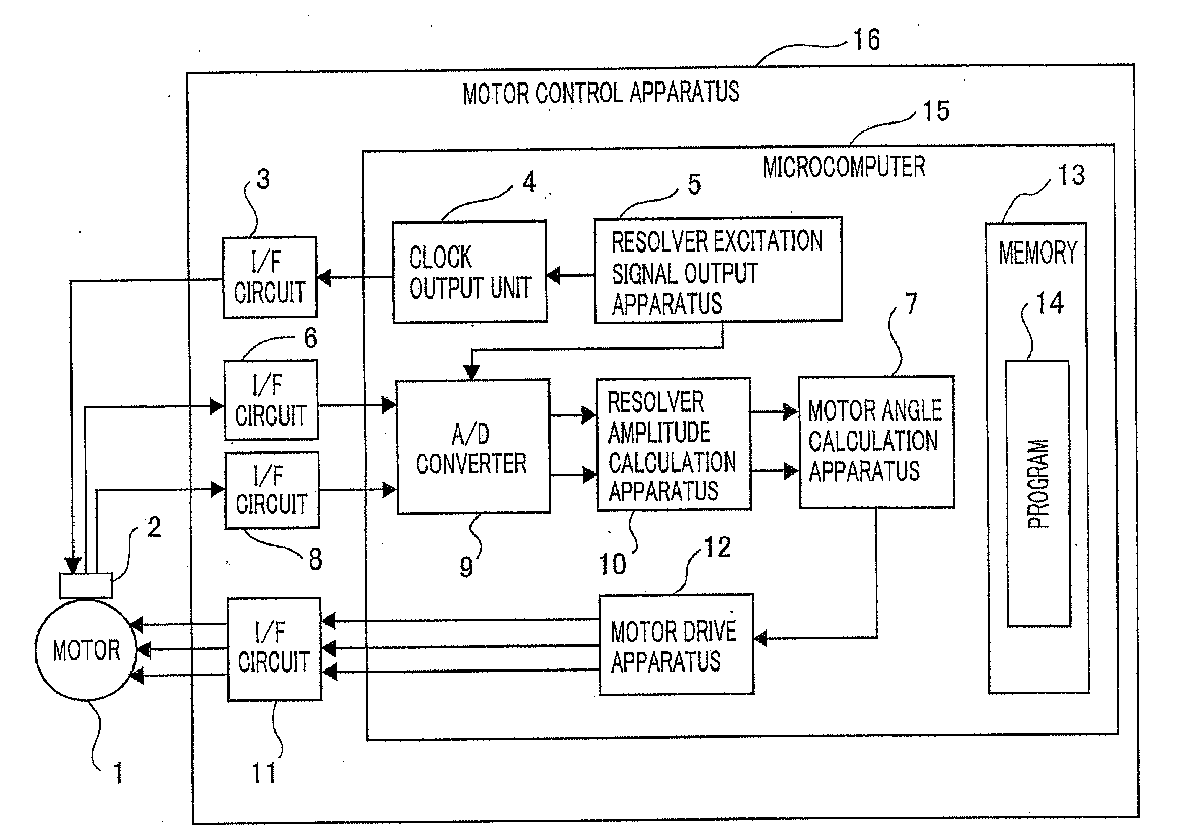
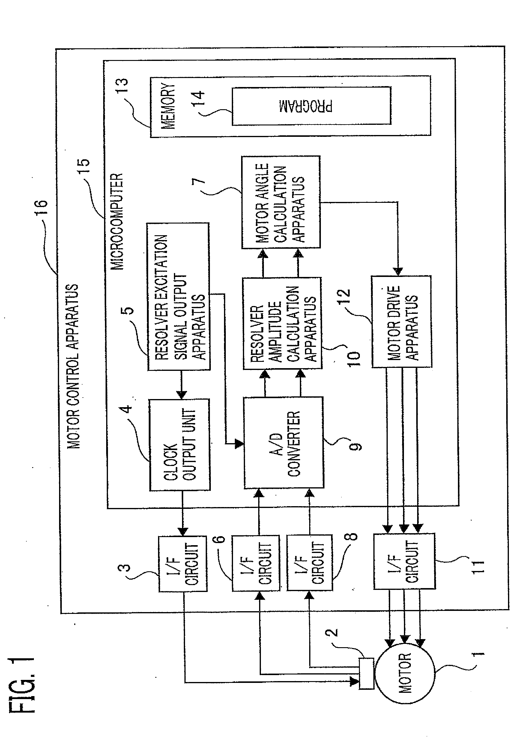
[0028]FIG. 1 is a system configuration diagram of a brushless motor rotation-position detection system according to Embodiment 1 of the present invention. In FIG. 1, a brushless motor rotation-position detection system according to Embodiment 1 is provided with a motor controller 16 for driving a brushless motor 1 and a resolver 2 for detecting the motor position of the brushless motor 1, which is a control subject. The motor controller 16 is provided with an interface circuit 3 (referred to only as an I / F circuit, hereinafter) for exciting the resolver 2, an I / F circuit 6 for receiving a sine wave signal outputted by the resolver 2, an I / F circuit 8 for receiving a cosine wave signal outputted by the resolver 2, an I / F circuit 11 for driving the brushless motor 1, and a microcomputer (referred to also as a calculation means, hereinafter) 15 that performs calculation for controlling the motor, based on rotation-position information on the brushless motor 1.

[0029]The microcomputer 15...

embodiment 2

[0036]Next, there will be explained Embodiment 2 of the present invention with reference to FIGS. 5 through 8. The configuration diagram of the system according to Embodiment 2 is the same as that of the system according to Embodiment 1.

[0037]At first, in a time that is half of the excitation period T for the resolver, the processing represented in FIG. 6 is called up. In FIG. 6, it is determined in the step S801 whether or not the present timing is a reference-voltage learning timing. In Embodiment 2, unlike Embodiment 1, each of the sine wave signal and the cosine wave signal is A / D-converted only at one side timing (only when the excitation signal is the maximum value or the minimum value), as represented in (d) and (f) of FIG. 5. Accordingly, for the purpose of obtaining the sine wave amplitude and the cosine wave amplitude, it is required that the calculations expressed by Equations (6) and (7) are performed by utilizing the respective A / D-converted values and a reference volta...

embodiment 3

[0045]Next, there will be explained Embodiment 3 of the present invention with reference to FIG. 9. Embodiment 3 differs from Embodiment 2 in terms of reference-voltage learning processing; however, because the other processing is similar to that in Embodiment 2, only the reference-voltage learning processing will be explained.

[0046]At first, as is the case with Embodiment 2, in the case where it is determined in the step S801 that the present timing is the reference-voltage learning timing, the step S801 is followed by the step S1101. In the step S1101, excitation of the resolver is interrupted. When the excitation of the resolver is interrupted, each of the sine wave signal and the cosine wave signal becomes equal to the reference voltage. Accordingly, in the step S1102, A / D conversion is applied to the terminal to which the sine wave signal is inputted, and in the step S1103, the value obtained through the conversion is stored in a memory, as a sine wave reference voltage Vscen2....


PUM


Abstract

A rotation-position detection system according to the present invention is configured with a resolver mounted in a brushless motor and a motor controller. The motor controller outputs an excitation signal to the resolver and an A / D converter thereof alternately applies analogue / digital conversion to a sine wave signal and a cosine wave signal outputted from the resolver so that a rotation position of the motor is calculated.

Description

BACKGROUND OF THE INVENTION[0001]1. Field of the Invention[0002]The present invention relates to a rotation-position detection system for a brushless motor in which a resolver is mounted.[0003]2. Description of the Related Art[0004]In the case of a control system for controlling a brushless motor, in order to optimally control the brushless motor, there is required a means for detecting the rotation position of the brushless motor. As means for detecting the rotation position of a brushless motor, a hole IC, a resolver, and the like are commonly known. Because it can more accurately detect the rotation position of a brushless motor than a hole IC, the resolver is suitable for a system for suppressing torque fluctuation while the motor rotates or a system that performs servo control.[0005]With regard to a method of detecting the rotation position of a brushless motor by use of a resolver, Japanese Patent Application Laid-Open No. 2005-210839 discloses a method utilizing a dedicated r...

Claims


Application Information

Patent Timeline
Patent Type & Authority Applications(United States)
IPC IPC(8): H02P6/16H03M1/48
CPCH02P6/001H03M1/645H03M1/1225H02P6/16H02P6/34
Inventor SAKAGUCHI, RYOITOI, MAKOTO
Owner MITSUBISHI ELECTRIC CORP
Why Eureka
Try Eureka