Device at fixing means for fixation of bone fragments at bone fractures

a technology for fixing means and bone fragments, which is applied in the field of devices for fixing means for fixing bone fragments at bone fractures, can solve the problems of poor arcuate shape of sleeves, often even straight parts, and inability to achieve optimal form of parts being forced ou

Active Publication Date: 2011-04-26
HANSSON
View PDF14 Cites 7 Cited by
  • Summary
  • Abstract
  • Description
  • Claims
  • Application Information

AI Technical Summary

Benefits of technology

[0004]Since the two front parts of the pin, which can be pressed out of the sleeve, have a successively increasing thickness in backwards direction towards the rear parts of the pin, several essential advantages are obtained, namely
[0005]a) that the two front parts of the pin being forced or pressed into the bone material, get an advantageous grip therein,
[0006]b) that there will be no risk th

Problems solved by technology

These front parts of the pins are of uniform thickness, which has resulted in that they when being forced out of the sleeve are formed into poorly arcuate and often even straight parts, particularly if the spike is ma

Method used


Image

  • Device at fixing means for fixation of bone fragments at bone fractures
  • Device at fixing means for fixation of bone fragments at bone fractures
  • Device at fixing means for fixation of bone fragments at bone fractures

Examples


Embodiment Construction

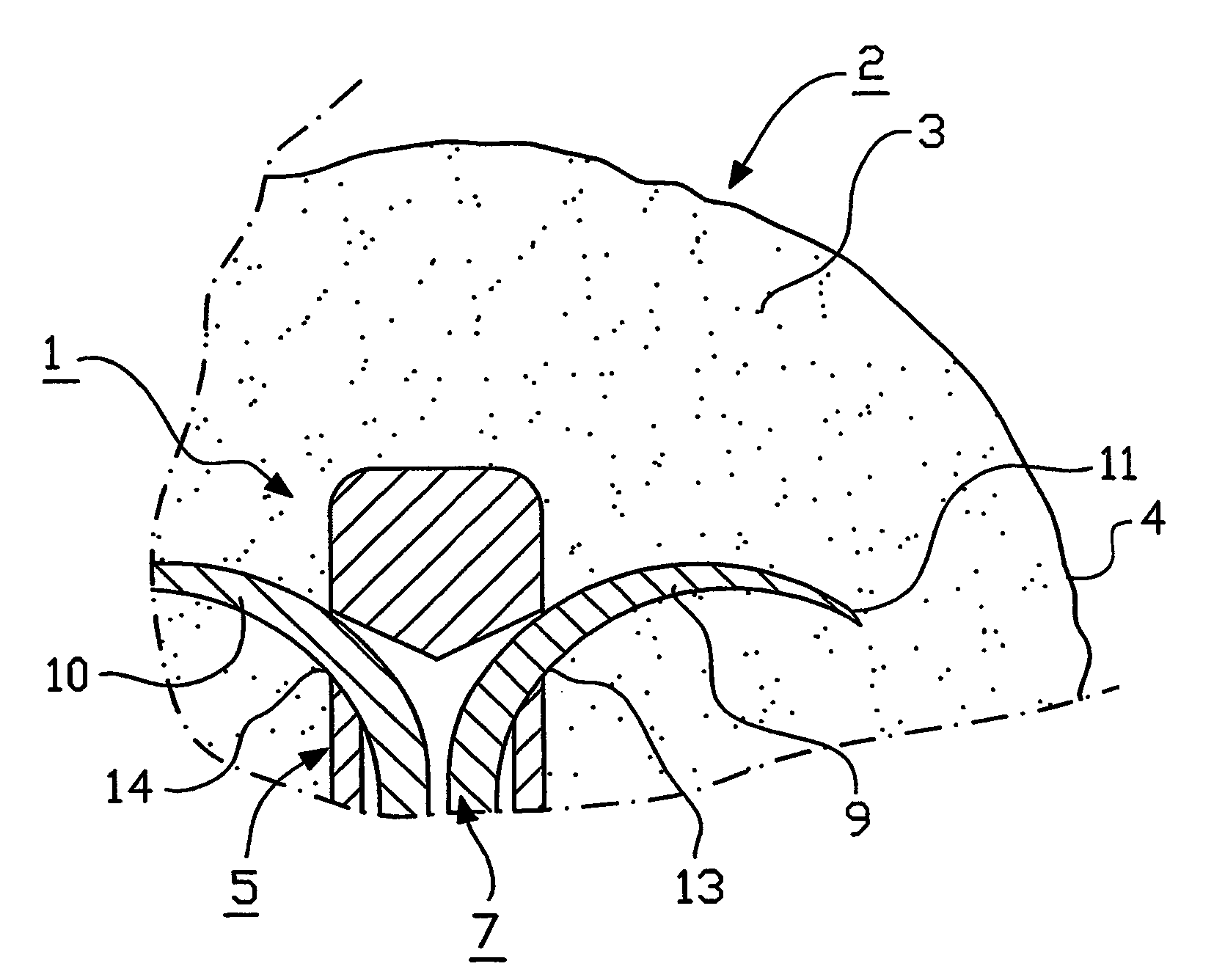
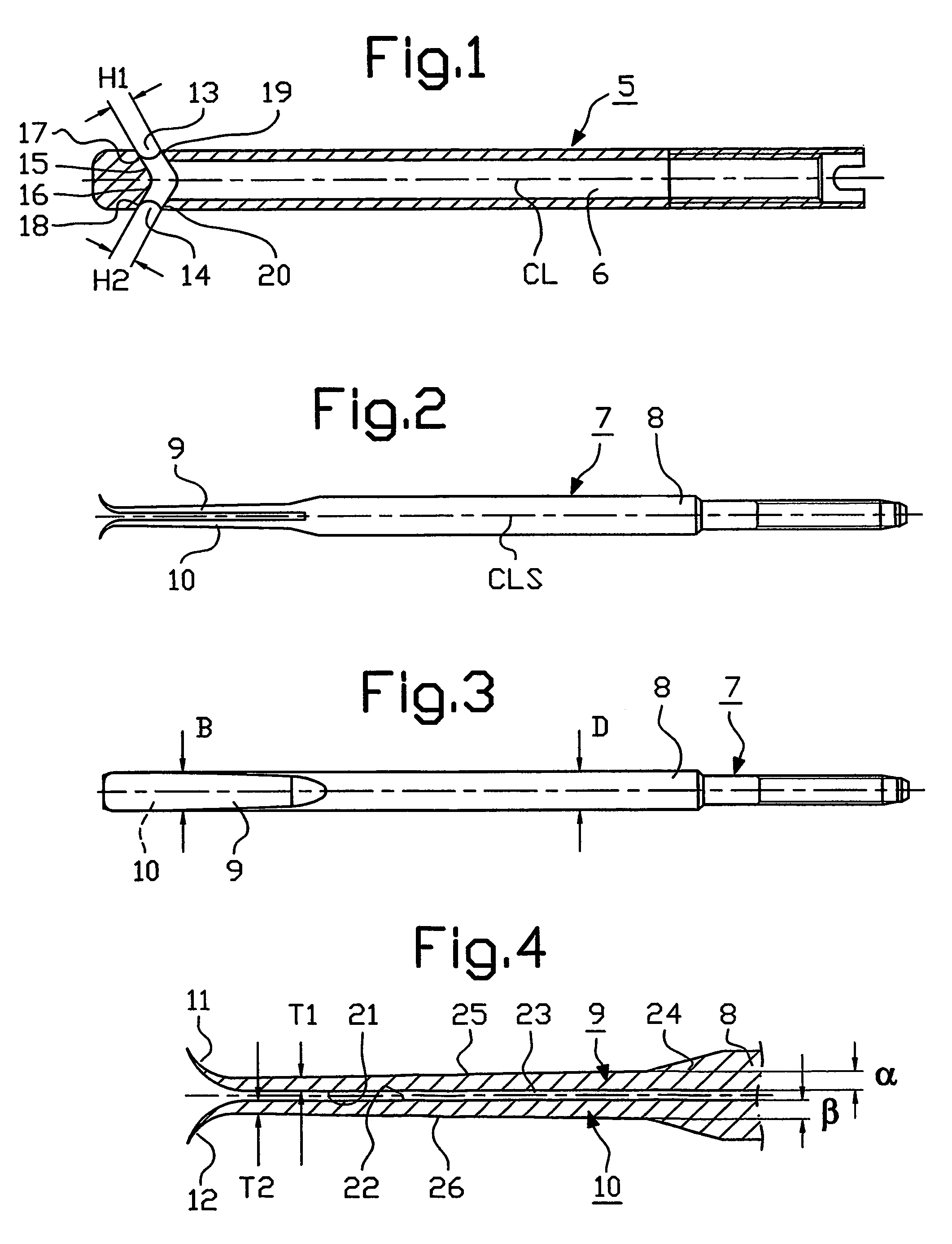
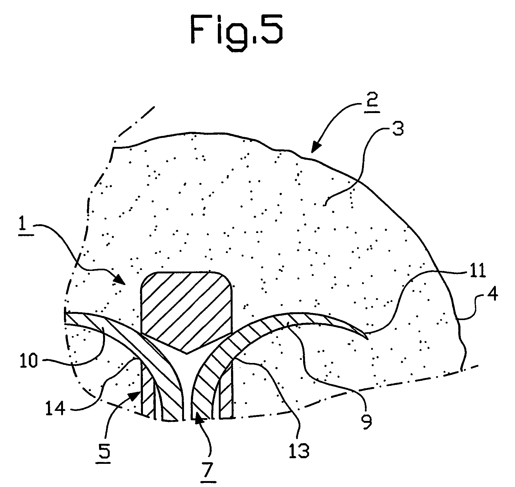
[0014]The fixing means 1 illustrated in the drawings is a collum or thigh-bone neck spike for fixation of bone fragments at trochantery hip fractures. In FIG. 5, front parts of this spike are shown located in the bone material 3 of the thigh-bone head 2 within the joint surfaces 4 of the thigh-bone head. The fixing means 1 has a sleeve 5 with a longitudinal space 6 which is open at the rear for insertion of a pin 7. The pin 7 is displaceable in the longitudinal direction of the sleeve 5 and has a rear part 8 and two front parts 9, 10 which extend from said rear part 8 in forward direction. Each front part 9, 10 has, at the front, a bent point or tip 11, 12 and these points 11, 12 are directed away from each other.

[0015]Front parts of the sleeve 5 have two openings 13, 14 which are located on opposite sides of said sleeve 5. One of the front parts 9 and 10 respectively, of the pin 7 can be forced out of the sleeve 5 through each opening 13 and 14 respectively, therein, by driving the...


PUM


Abstract

The present invention relates to a device at fixing means for fixation of bone fragments at bone fractures, the fixing means (1) preferably being a spike for fixation of bone fragments at trochantery hip fractures. The fixing means (1) comprises a sleeve (5) and a pin (7) which is insertable into the sleeve (5) and displaceable in the longitudinal direction thereof. The pin (7) has a rear part (8) and at least two front parts (9, 10) with bent points or tips. Front parts of the sleeve (5) have openings (13, 14) through which the front parts (9, 10) of the pin (7) can be forced. The front parts (9, 10) of the pin (7) have a successively increasing thickness in backwards direction towards the rear part (8) of the pin (7) such that said front parts (9, 10), when forced or driven out of the sleeve (5) through the openings (13, 14), are formed into arcuate parts, the points (11, 12) of which are curved in backwards direction or substantially backwards relative to a geometric centre line along the pin (7), and such that those portions of the front parts (9, 10) which after said outward driving of the front parts (9, 10) are situated at the sleeve (5), are thicker and thereby stronger than those portions of the front parts (9, 10) which grip into the bone material (3).

Description

FIELD OF THE INVENTION[0001]The present invention relates to a device at fixing means for fixation of bone fragments at bone fractures, said fixing means preferably being a spike for fixation of bone fragments at trochantery hip fractures. The fixing means comprises a sleeve and a pin which is insertable into the sleeve and displaceable in the longitudinal direction thereof. The pin has a rear part and at least two front parts. The front parts are provided with bent points or tips and front parts of the sleeve have openings through which the front parts of the pin can be forced.BACKGROUND OF THE INVENTION[0002]Fixing means for fixation of bone fragments at bone fractures are known from the publication WO 95 / 31942. This fixing means comprises a sleeve with two pins, the front parts of which can be forced out of the sleeve in opposite directions and into surrounding bone material. These front parts of the pins are of uniform thickness, which has resulted in that they when being forced...

Claims


Application Information

Patent Timeline
IPC IPC(8): A61B17/72A61B17/78
CPCA61B17/744A61B17/7266
Inventor HANSSON
Owner HANSSON
Why Eureka
Try Eureka