
Flowmeter calibration system and operational method

a fluid flowmeter and calibration system technology, applied in the calibration of speed/acceleration/shock measurement devices, measurement devices, instruments, etc., can solve the problems of not providing optimization of calibration methods to minimize, and the volumetric fluid flow rate standards for fluid flowmeter calibration of directional piston displacement type volumetric fluid flow rate calibration do not provide the effect of optimizing calibration methods, reducing uncertainty, and reducing the ratio of connecting volum

Inactive Publication Date: 2011-05-03
WINCHESTER JAMES EDWARD
View PDF8 Cites 13 Cited by
  • Summary
  • Abstract
  • Description
  • Claims
  • Application Information

AI Technical Summary

Benefits of technology

This approach significantly reduces the uncertainty of fluid flow rates at the meter under test, allowing for more precise calibration with reduced calibration time and improved thermal stability, ensuring a predetermined level of uncertainty for the average volumetric fluid flow rate.

Problems solved by technology

However, in no case can the uncertainty of measurement for a given flowmeter be considered better than the standard and process against which it has been calibrated.
Prior art bi-directional piston displacement type volumetric fluid flow rate standards for calibration of fluid flowmeters do not provide optimization of calibration method to minimize the uncertainty of flow rate at meters under test for each delivered standard volume of fluid.
Prior art bi-directional piston displacement type volumetric fluid flow rate standards for calibration of fluid flowmeters do not control the standard volume value on the basis of temperature measurement uncertainty, connecting volume value and fluid and connecting volume piping thermal expansion coefficients and other physical parameters contributing to uncertainty to assure that each delivered standard volume achieves a predetermined level of uncertainty for the average volumetric fluid flow rate at the meter under test.

Method used


Image

  • Flowmeter calibration system and operational method
  • Flowmeter calibration system and operational method
  • Flowmeter calibration system and operational method

Examples


Embodiment Construction

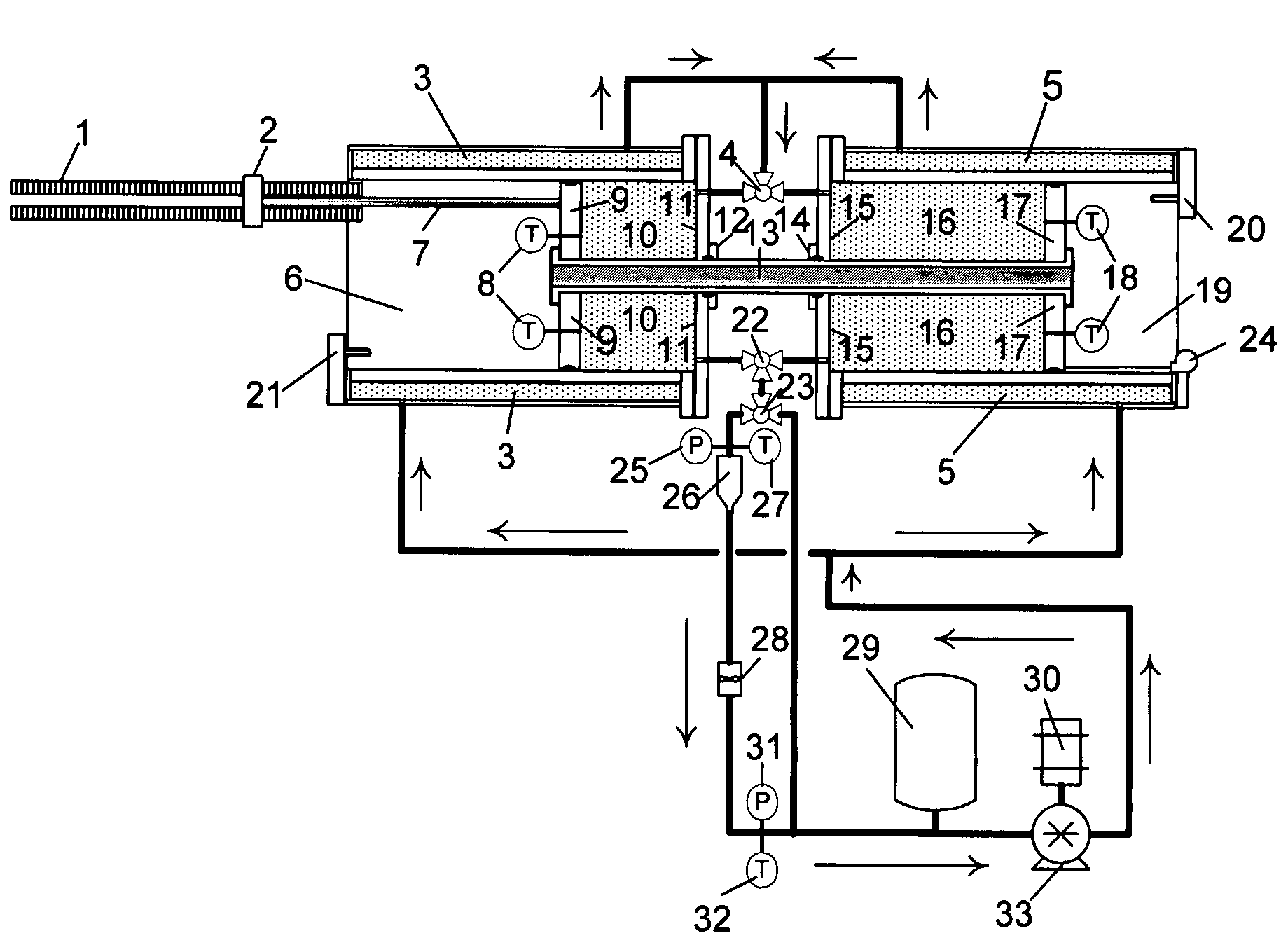
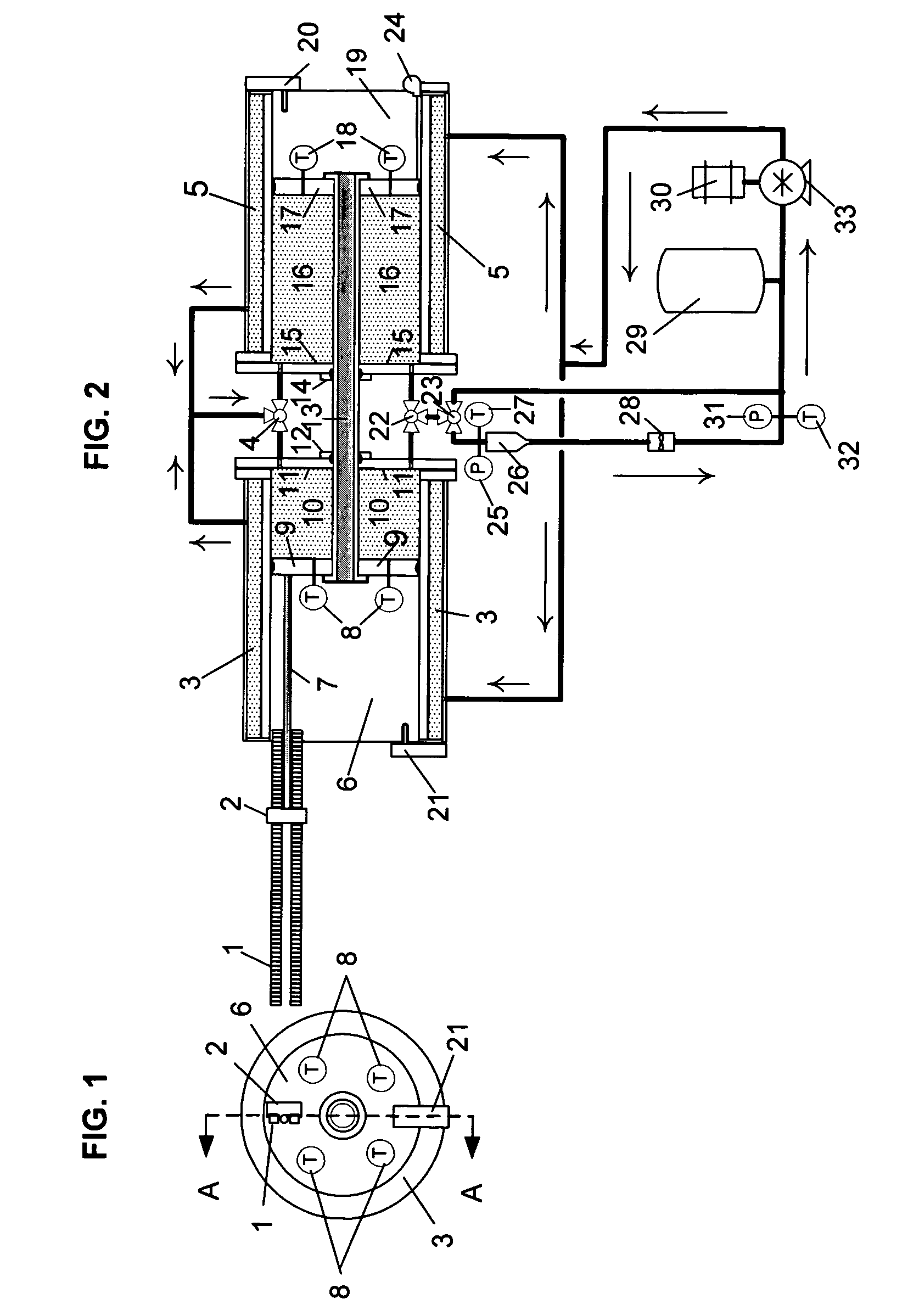
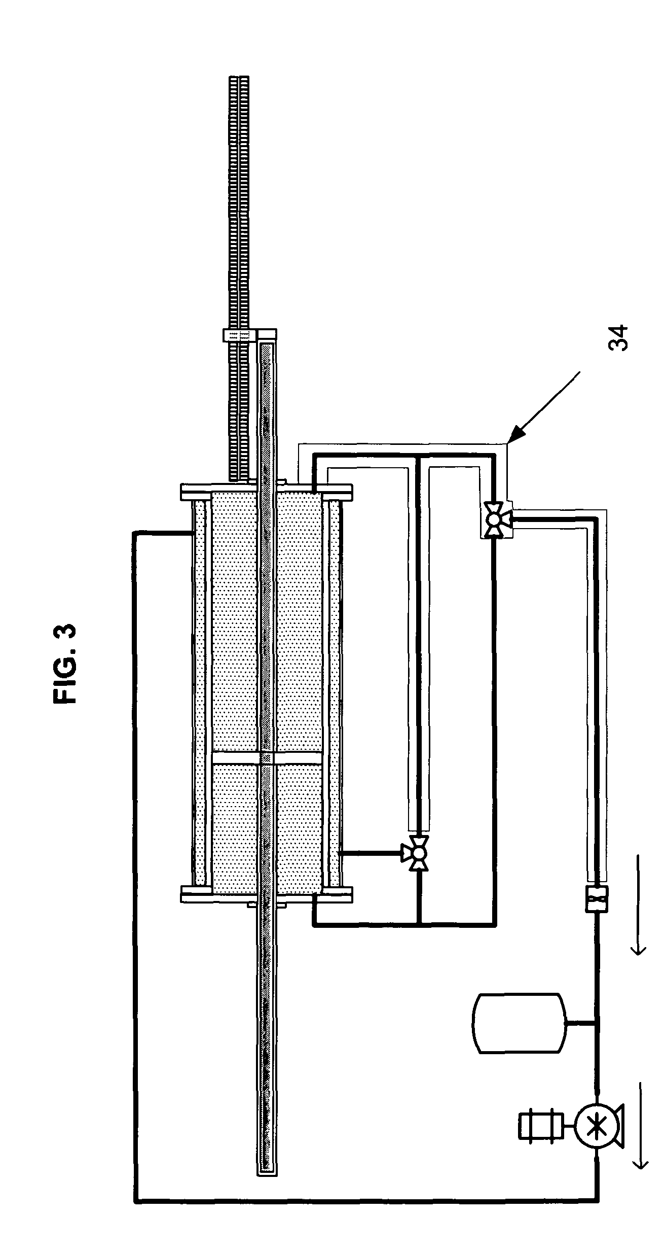
[0045]In the first embodiment of the present invention for liquid service, two cylinders 6 and 19, each containing a fluid barrier piston 9 and 17, are axially aligned. The two pistons 9 and 17 are mechanically coupled via an interconnecting shaft 13 and move in unison as directed by the force of fluid being pumped into the cylinder chamber 10 or 16 receiving said fluid via three-way valve 4 after said fluid has passed under pressure through the jacketed volumes 3 and 5 surrounding the exteriors of both cylinders 6 and 19. The interconnecting shaft 13 passes through end plates 11 and 15 on the fluid chamber 10 or 16 end of the cylinders 6 or 19 via fluid barrier sealing mechanisms 12 and 14 around the outer surface of the shaft 13. The pressure of the fluid acting on the piston 9 or 17 in the cylinder fluid chamber 10 or 16 receiving the pumped fluid creates a motive force on the piston 9 or 17 in the second cylinder 6 or 19 via the mechanical coupling of the interconnecting shaft 1...


PUM


Abstract

Disclosed is a bi-directional piston displacement type volumetric fluid flow rate delivery and metering system (calibration standard) and operational method for calibration of fluid flowmeters. The present invention provides reduced uncertainty of delivered volumetric fluid flow rate at meters under test relative to the uncertainty of volumetric fluid flow rate at meters under test provided by prior art bi-directional piston displacement type volumetric fluid flow rate standards given the same nominal cylinder diameters and working fluid and equal dimensional, timing and temperature measurement uncertainties by employing a plurality of metering pistons and cylinders to minimize the connecting volume piping between the metering piston cylinder outlet and meters under test, providing open access to one side of each metering piston to accomplish installation of temperature probes through the pistons into the working fluid and by operational method which minimizes the connecting volume to standard volume ratio.

Description

FIELD OF THE INVENTION[0001]The present invention relates to a laboratory calibration system and operational method for characterization of fluid flowmeters. Specifically, the present invention is an improved system and operational method over prior art bi-directional piston displacement type volumetric fluid flow rate standards providing reduced uncertainty of volumetric fluid flow rate delivered to a meter under test over what can be achieved with prior art bi-directional piston displacement type volumetric fluid flow rate standards given the same nominal cylinder diameter and working fluid and equal dimensional, timing and temperature measurement uncertainties. Working fluid is defined as the fluid that is metered and passed through a flowmeter being calibrated. A flowmeter being calibrated is herewith referred to as a flowmeter under test or simply a meter under test.BACKGROUND OF THE RELATED ART[0002]Delivering volumetric fluid flow to a meter under test by metering the fluid f...

Claims


Application Information

Patent Timeline
Patent Type & Authority Patents(United States)
IPC IPC(8): G01F25/00
CPCG01F25/003G01F25/13
Inventor WINCHESTER, JAMES EDWARD
Owner WINCHESTER JAMES EDWARD
Learn More