Multi-sectional airtight seal for continuous air-filling and air valve device thereof

a technology of air valve and continuous air filling, which is applied in the direction of liquid handling, packaging goods type, paper/cardboard articles, etc., can solve the problems of inability to absorb or buffer a greater vibration or impact load, the capacity of the tiny gasbag to be unable to fill, and the shock absorption capacity of the tiny gasbag to be limited

Inactive Publication Date: 2011-05-03
LIAO CHIEH HUA
View PDF19 Cites 13 Cited by
  • Summary
  • Abstract
  • Description
  • Claims
  • Application Information

AI Technical Summary

Benefits of technology

[0012]By means of configuring the first valve devices and the second valve devices, external air is allowed to enter and expand the first sub-tubes and the second sub-tubes at the same time. Not only filling speed of the first sub-tubes and the second sub-tubes is faster, the shock-absorption and cushion capabilities are also maintained by the checking capability of the first valve devices and the second valve devices without leaking from other air tubes when any of the air tubes is broken.
[0014]By providing a structure of the air valve device equipped with the first filling passage and the second filling passage, external air is allowed to fill through the first filling passage and expand one of the air tubes, and meanwhile another of the air tubes is filled through the second filling passage to be expanded. The filling speed of the air tubes is accelerated, and the shock-absorption and cushion capabilities are also maintained without leaking from other air tubes when any of the air tubes is broken.

Problems solved by technology

However, the tiny gasbags have limited shock-absorption capability and fail to absorb or buffer a greater vibration or impact load.
However, the air valve A14 of the air-packing bag A10 is not capable of filling the plural chambers A13.

Method used


Image

  • Multi-sectional airtight seal for continuous air-filling and air valve device thereof
  • Multi-sectional airtight seal for continuous air-filling and air valve device thereof
  • Multi-sectional airtight seal for continuous air-filling and air valve device thereof

Examples


first embodiment

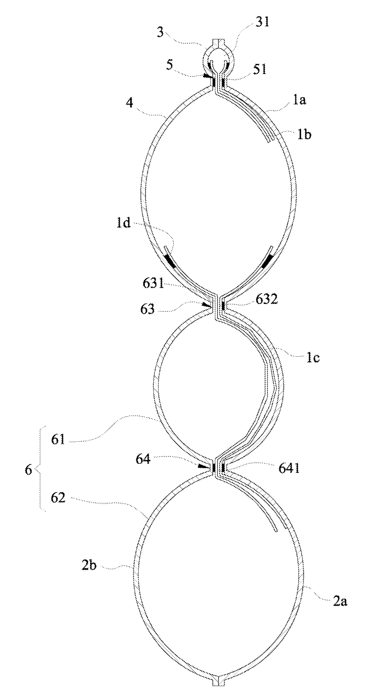
[0037]Please refer to FIGS. 4, 5, 5A and 6, which illustrate a multi-sectional airtight seal for continuous air-filling. FIG. 4 is a plane view before filling air; FIG. 5 is a cross sectional view after filling air; FIG. 5A is a cross sectional view for the portion A in FIG. 5; FIG. 6 is a perspective view after filling air.

[0038]The multi-sectional airtight seal for continuous air-filling includes an input passage 3, plural main air tubes 4, plural single-path valve devices 5, and plural auxiliary tubes 6.

[0039]The input passage 3 is operative as space formed by thermal-sealing the two outer films 2a and 2b, or space formed by thermal-sealing the two inner films 1a and 1b. The input passage 3 includes a pneumatic hole 31 for filling external air.

[0040]The plural main air tubes 4 are operative as air storage formed by thermal-sealing the two outer films 2a, 2b. The plural main air tubes 4 are aligned parallel to a lateral side of the input passage 3.

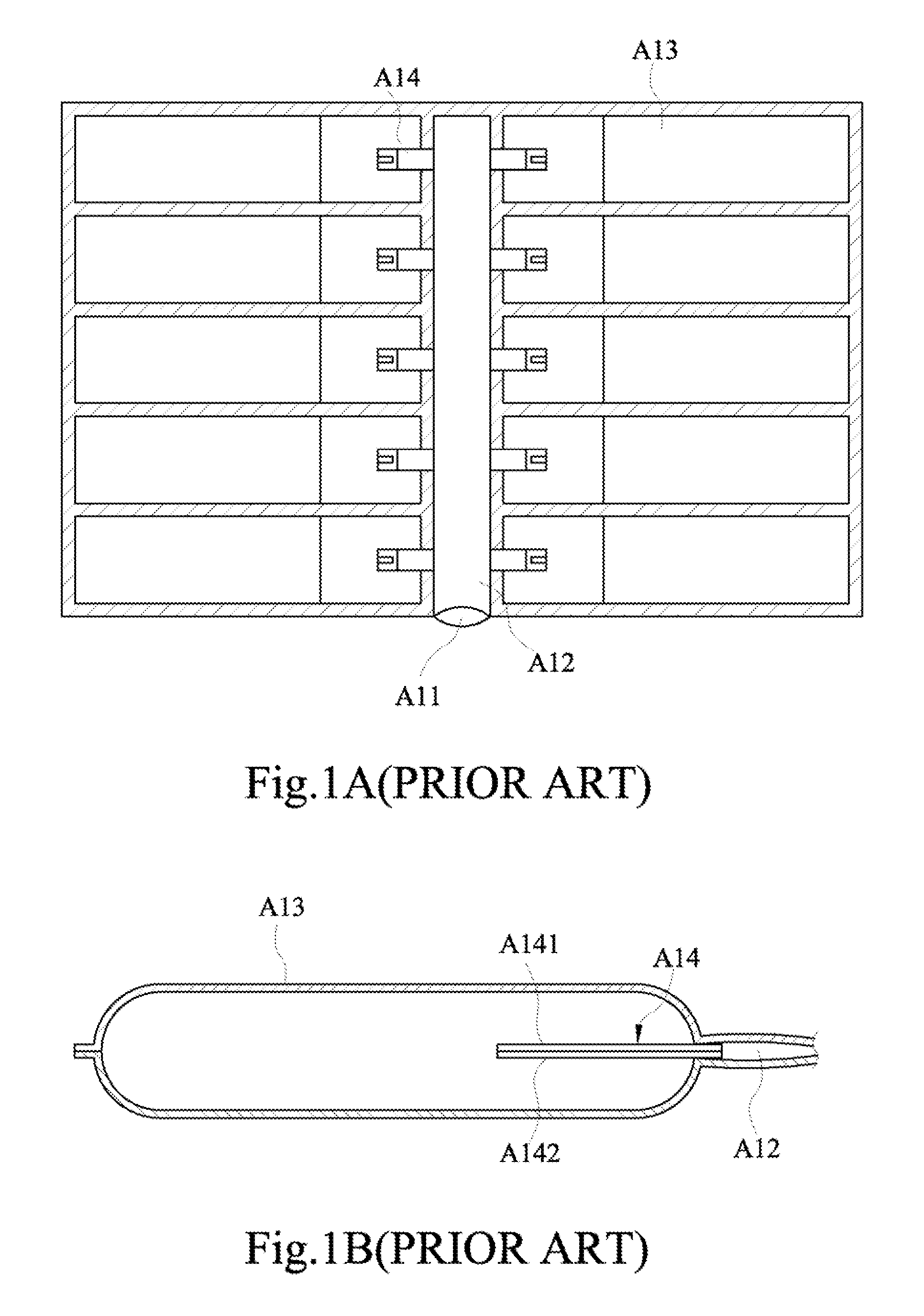
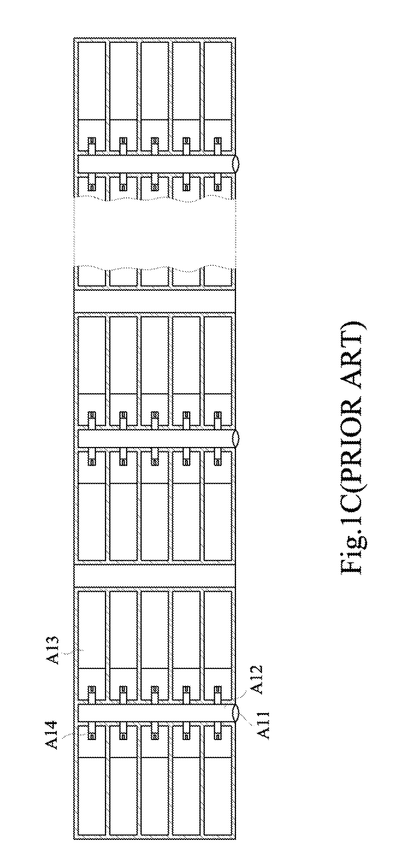
[0041]The plural single-path valv...

second embodiment

[0051]Please refer to FIG. 7, which is a cross sectional view according to a multi-sectional airtight seal for continuous air-filling after filling air.

[0052]In the second embodiment, plural single-path valve devices 5 are formed by applying heatproof material between the two inner films 1a, 1b and thermal-sealing the two inner films 1a, 1b, thereby providing airflow passages through the heatproof material. The second valve device 64 is formed by applying heatproof material between the two inner films 1d, 1e and thermal-sealing the two inner films 1d, 1e. The second valve device 64 includes a filling passage 641 for connecting the second sub-tube 62 and the second filling passage 632 to allow through-linking between the second sub-tube 62 and the main air tube 4.

[0053]In the structure described above, each of the plural single-path valve devices 5 may be formed by applying heatproof material between one of the inner films 1a and one of the outer films 2a, and by thermal-sealing one ...

third embodiment

[0054]Please refer to FIG. 8, which is a plane view according to a multi-sectional airtight seal for continuous air-filling before filling air.

[0055]The first valve device 63 of each of the plural auxiliary tubes 6 includes the first filling passage 631 and the second filling passage 632; wherein the first filling passage 631 is formed by applying heatproof material between one of the inner films 1d and one of the outer films 2, and by thermal-sealing one of the inner films 1d and one of the outer films 2b thereby connecting the first sub-tube 61 and the main air tube 4. The second filling passage 632 is formed by applying heatproof material between the two inner films 1c, 1d, and thermal-sealing the two inner films 1c, 1d. The second valve device 64 is formed by thermal-sealing the two inner films 1c, 1d. The second valve device 64 includes a filling passage 641 for connecting the second sub-tube 62 and the second filling passage 632, thereby allowing through-linking between the se...


PUM

PropertyMeasurementUnit
lengthsaaaaaaaaaa
timeaaaaaaaaaa
structureaaaaaaaaaa

Abstract

A multi-sectional airtight seal for continuous air-filling includes: an input passage; plural first sub-tubes aligned parallel to a lateral side of the input passage; plural first valve devices including a first filling passage and a second filling passage with the first filling passage connecting the first sub-tubes and the input passage; plural second sub-tubes serially connecting the first sub-tubes; and plural second valve devices for connecting the second sub-tubes and the second filling passages to allow through-linking between the second sub-tubes and the input passage. When external air in the input passage enters through the first filling passage of the first valve device to fill and expand the first sub-tubes, the second sub-tube is filled through the second filling passage and the second valve device to be expanded as well.

Description

BACKGROUND OF THE INVENTION[0001]1. Field of Invention[0002]The present invention relates to airtight seal and air valve device, and more particularly to a multi-sectional airtight seal for continuous air-filling and an air valve device thereof.[0003]2. Related Art[0004]A convention way for buffer packing is mostly to use a plastic sheet configured with plural raised tiny gasbags to cover outside an article and achieve shock-absorption and cushion effects. However, the tiny gasbags have limited shock-absorption capability and fail to absorb or buffer a greater vibration or impact load. Therefore, an air-packing bag made of resin film was developed.[0005]Please refer to FIGS. 1A-1C. An air-packing bag A10 includes an input hole A11 and a filing path A12 connecting with the input hole A11. Both sides of the filing path A12 connect with plural chambers A13 respectively. Each of the chambers A13 is configured with an air valve A14 composed by a upper valve film A141 and a lower valve fi...

Claims


Application Information

Patent Timeline
Patent Type & Authority Patents(United States)
IPC IPC(8): B65B3/16
CPCB65D81/052B31D5/0078B65D31/14B65D81/03
Inventor LIAO, CHIAN HUALIAO, YAO SINLIAO, YAO CHUAN
Owner LIAO CHIEH HUA
Why Eureka
Try Eureka