Rack for transport and storage

a rack and rack technology, applied in the field of collapsible racks, can solve the problems of difficult to ensure the parallelity of the panels carrying difficult to ensure the parallelity of the panels, and difficulty in ensuring the quality of the printed circuit boards, so as to achieve the effect of reducing the number of moveable parts, cost-effective, and stable carrier for sensitive components

Inactive Publication Date: 2011-05-03
SCHOELLER ARCA SYST
View PDF11 Cites 2 Cited by
  • Summary
  • Abstract
  • Description
  • Claims
  • Application Information

AI Technical Summary

Benefits of technology

The present invention aims at solving the above problems by providing a collapsible rack which minimizes the number of moveable parts and ensures a stable carrier for sensitive components. It has through the present invention been made possible to solve the above problems and a collapsible, sturdy and cost effective rack has been brought about.
The distance bar preferably comprises a bar section and two end sections. The bar section slides into a bar hole on each of the end sections. This allows the rack to easily be designed for the desired printed circuit board width by only changing the bar section. The end sections are suitably provided with a locking hole and a lock screw arranged perpendicular to the bar section. This allows the width of the rack to be locked after having been adjusted to exact width. The screw may have a conical tip which is pressed into the face of the bar section. The threads in the locking hole are suitably tight enough to prevent the screw from getting loose. It also possible to lock the screw with cyanoacrylate glue or the like. It is finally suitable to use a cap to cover the open end of the locking hole to prevent unauthorized tampering with the locking screw. This cap may even be molded together with, and attached to, the end section via a so-called live hinge
The clutching sections are preferably tapered and the hole is also tapered to match the clutching section. This will minimize any play in the rack which otherwise would be wobbly. Wear and tear will not have effect on such a design and the stability will be kept within the desired range for a very long time. The taper is suitably larger than 1° as seen from the insertion axis. Accordingly, both the hole and the clutching section have a conical shape and the angle of the side faces are adapted so that the parts do not wedge hard enough to cause problems. The angle should be adapted to the material selected, but normally an angle above 2-4° should be without problems.
The first and second panels are suitably provided with a channel which runs between the third and fourth edges as well as parallel to the first and second edges and ends with the holes on said third and fourth edges. This channel is then suitably arranged adjacent to the first edge. This cannel may suitably be so designed that an end plug containing the hole intended to match the clutching section is inserted in the end of the channel. It will hereby be a rather simple task to insert a spring between the two opposite clutching sections, pulling the two together. It is also rather easy to insert a stopper in the form of a washer or a pin on the inside of the end plug which, as desired, limits the outward movement of the clutching section.

Problems solved by technology

This rack is foldable but have a great number of hinges which will make it very difficult to ensure parallelity between the panels carrying the printed circuit boards.
It will furthermore be very difficult to ensure that the panels and the arms connecting them relate to one another perpendicular as seen from above.
The design is also rather complicated and therefore costly.
However, this would require special skill and training of the personnel as well as an increased wear and tear of the different parts would occur.
There is also a risk of loosing parts and tolerances in an assembled rack would inevitably be hampered.

Method used


Image

  • Rack for transport and storage
  • Rack for transport and storage
  • Rack for transport and storage

Examples


Embodiment Construction

The invention is described further in connection to enclosed figures showing different embodiments of the invention whereby,

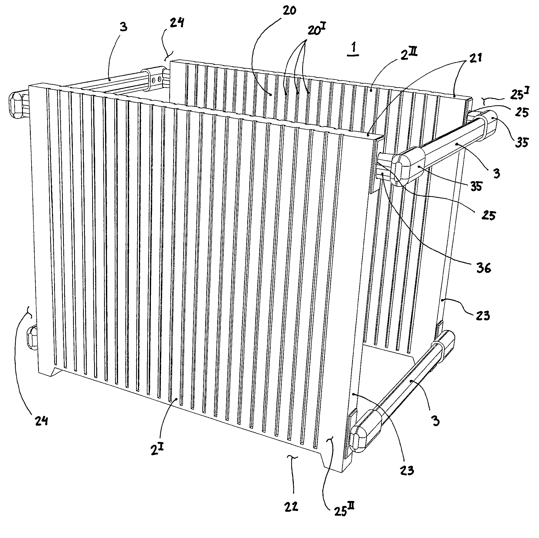
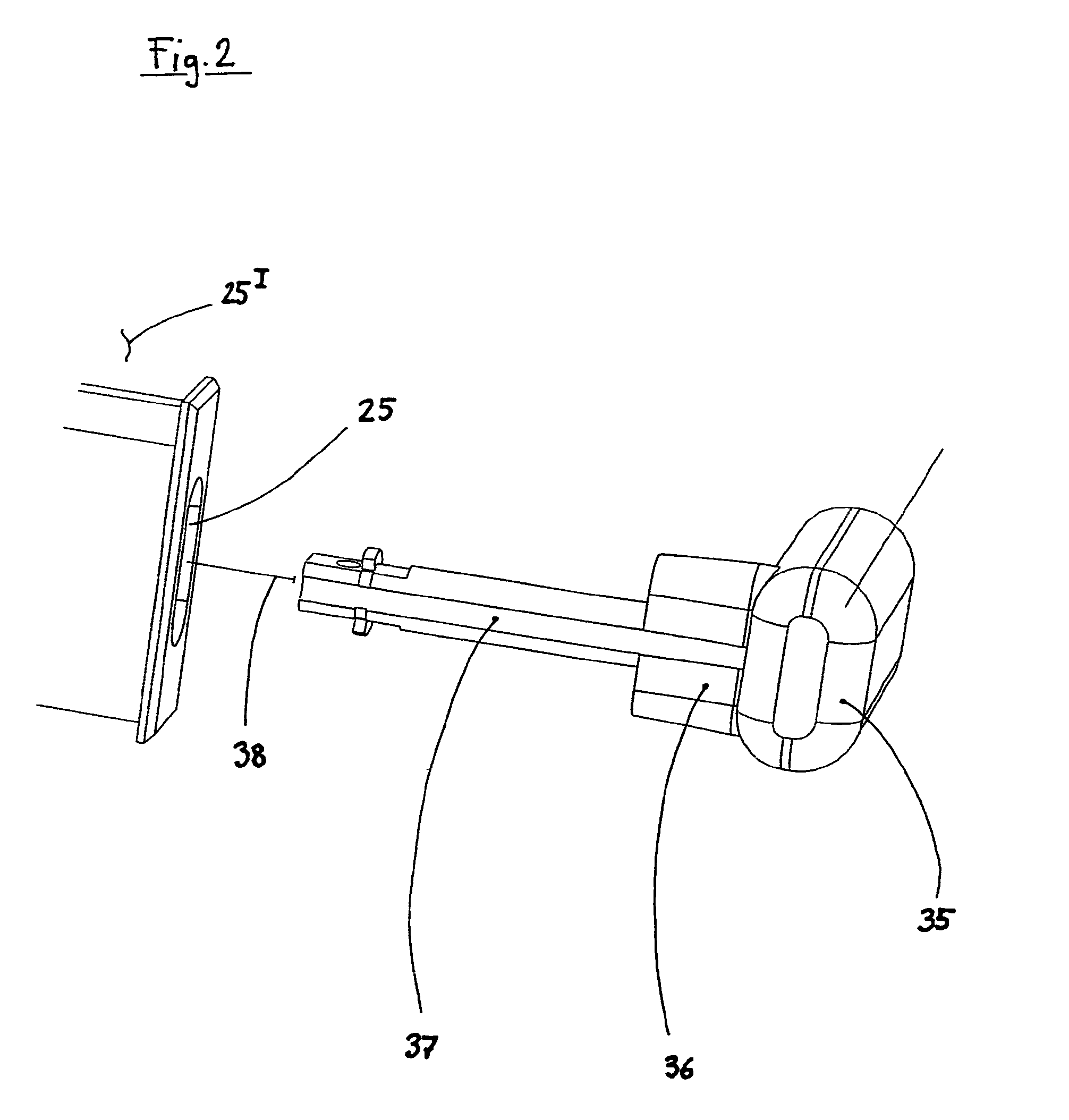
FIG. 1 shows, in perspective view, a collapsible rack 1 according to the invention.

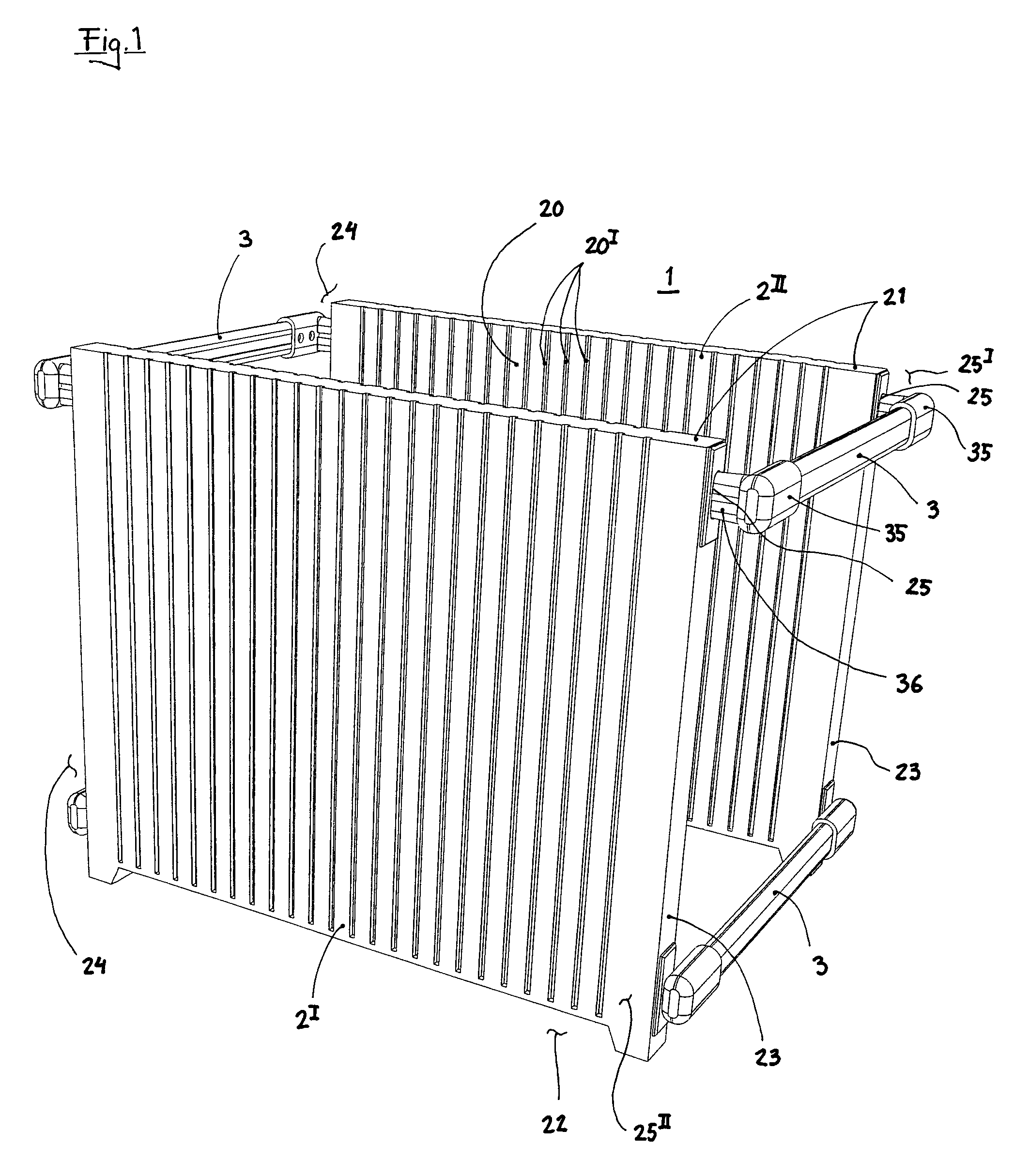
FIG. 2 shows, in perspective blown view, an upper portion of a collapsible rack 1 according to the invention where a clutching section 36 and a hole 25 is parted.

FIG. 3 shows, in perspective blown view, an lower part of a collapsible rack 1 according to the invention where a coupler 35I and a coupler hole 25B is parted.

Accordingly, FIG. 1 shows a collapsible rack 1 for transport an storage. The collapsible rack 1 is provided with a first and a second panel 2I and 2II respectively and a plurality of distance bars 3. The first and second panel 2I and 2II respectively, have a groove side 20 provided with a number of grooves 20I intended for receiving printed circuit boards. The panels 2I and 2II respectively have first and second edges 21 and 22 respectively, arranged on opposite si...


PUM


Abstract

A collapsible rack for transport and storage, includes a first and a second panel and a plurality of distance bars. The first and second panel include a groove side including at least one groove. A first and a second edge is arranged on opposite sides and adjacent to these, a third and a fourth edge. The third and fourth edges each include at least one hole that extends parallel to the first and second edges. The hole has a non-circular shape. The distance bars at each of their ends includes a hole coupling mechanism. The hole coupling mechanism extends perpendicular to the extension of the bar. The hole coupling mechanisms include clutching sections that match the hole, wherein pivoting between the bars and the first and second panel is prevented where the hole coupling mechanism and hole are fully mated.

Description

BACKGROUND OF THE INVENTION1. Field of the InventionThe present invention relates to a collapsible rack for transport and storage of flat or semi flat objects.2. Description of Related Prior ArtRacks for keeping flat objects organized and protected during transport and storage is a well known item. These racks are known from a number of different technical fields. We may here mention electronic industry where printed circuit boards with components installed often are stored and transported this way, both during assembly in so called surface mounting lines and for delivery of fully assembled and semi-assembled boards. Racks are also used during curing and similar treatment of the printed circuit board prior to installation of components. One such rack is known from U.S. Pat. No. 4,761,044 showing a rack which have an adjustable width. This will make it possible to adjust the rack for the specific printed circuit board currently in use. Another rack is known from U.S. Pat. No. 5,593,0...

Claims


Application Information

Patent Timeline
Patent Type & Authority Patents(United States)
IPC IPC(8): A47G19/08
CPCA47B47/00B65D15/22B65D11/1873B65D85/48H05K13/0069
Inventor YDSTROM, PER
Owner SCHOELLER ARCA SYST
Why Eureka
Try Eureka