
Display device, a front frame used therein, and a method of manufacture thereof

a technology of display device and front frame, which is applied in the direction of casing/cabinet/drawer details, casing/cabinet/drawer details of electrical apparatus, instruments, etc., can solve the problems of increasing the overall work time and cost required, creating local deformation in the outer frame, and insufficient accuracy, so as to reduce the deformation stress

Active Publication Date: 2011-05-03
AU OPTRONICS CORP
View PDF4 Cites 14 Cited by
  • Summary
  • Abstract
  • Description
  • Claims
  • Application Information

AI Technical Summary

Benefits of technology

[0008]It is an objective of the present invention to provide a front frame and a display device using the front frame to reduce the deformation stress of the front frame exerted on the active area of the display panel.
[0009]It is another objective of the present invention to provide a front frame and a display device using the front frame to reduce the production costs.
[0010]It is another objective of the present invention to provide a front frame and a display device using the front frame to reduce the assembly time.
[0011]It is another objective of the present invention to provide a manufacture method of display devices to reduce the production costs and the assembly time.
[0014]The front frame further includes cushion filler. The cushion filler is disposed in the groove. Top of the cushion filler protrudes from the groove and from the inner surface of the top plate. The cushion filler contact the outside of the active area. Disposition of the cushion filler reduces the occurrence of inferior displayed images caused by stresses of tip of the top plate exerted on the display device.

Problems solved by technology

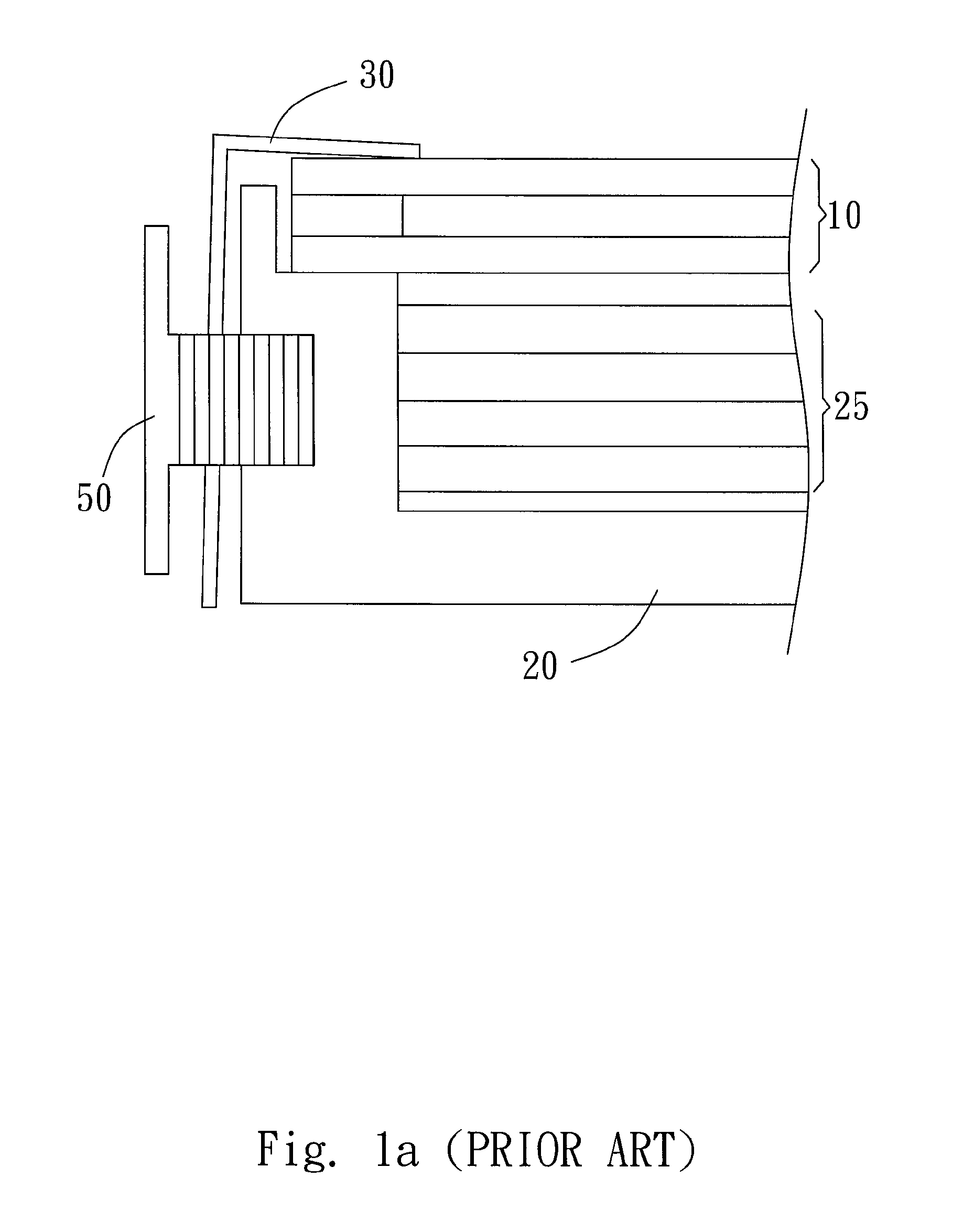
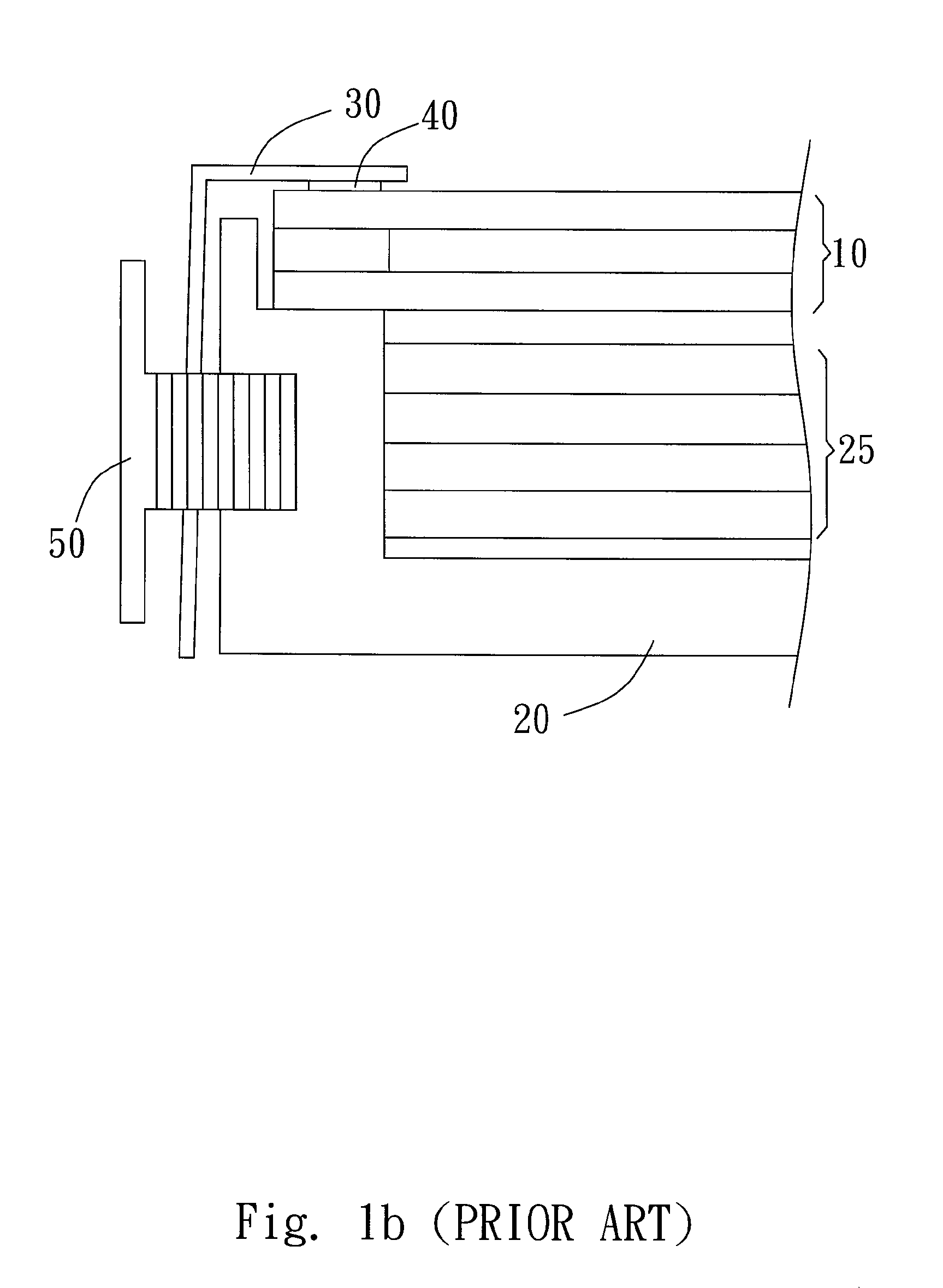
However, due to bad assembly or external forces, the stress exerted by the screw 50 may create local deformation in the outer frame 30.
However, the step of pasting the pad 40 is done manually and may increase the overall work time and costs required.
Furthermore, problem of insufficient accuracy in pad pasting may arise which further influences the overall quality of the products.

Method used


Image

  • Display device, a front frame used therein, and a method of manufacture thereof
  • Display device, a front frame used therein, and a method of manufacture thereof
  • Display device, a front frame used therein, and a method of manufacture thereof

Examples


Embodiment Construction

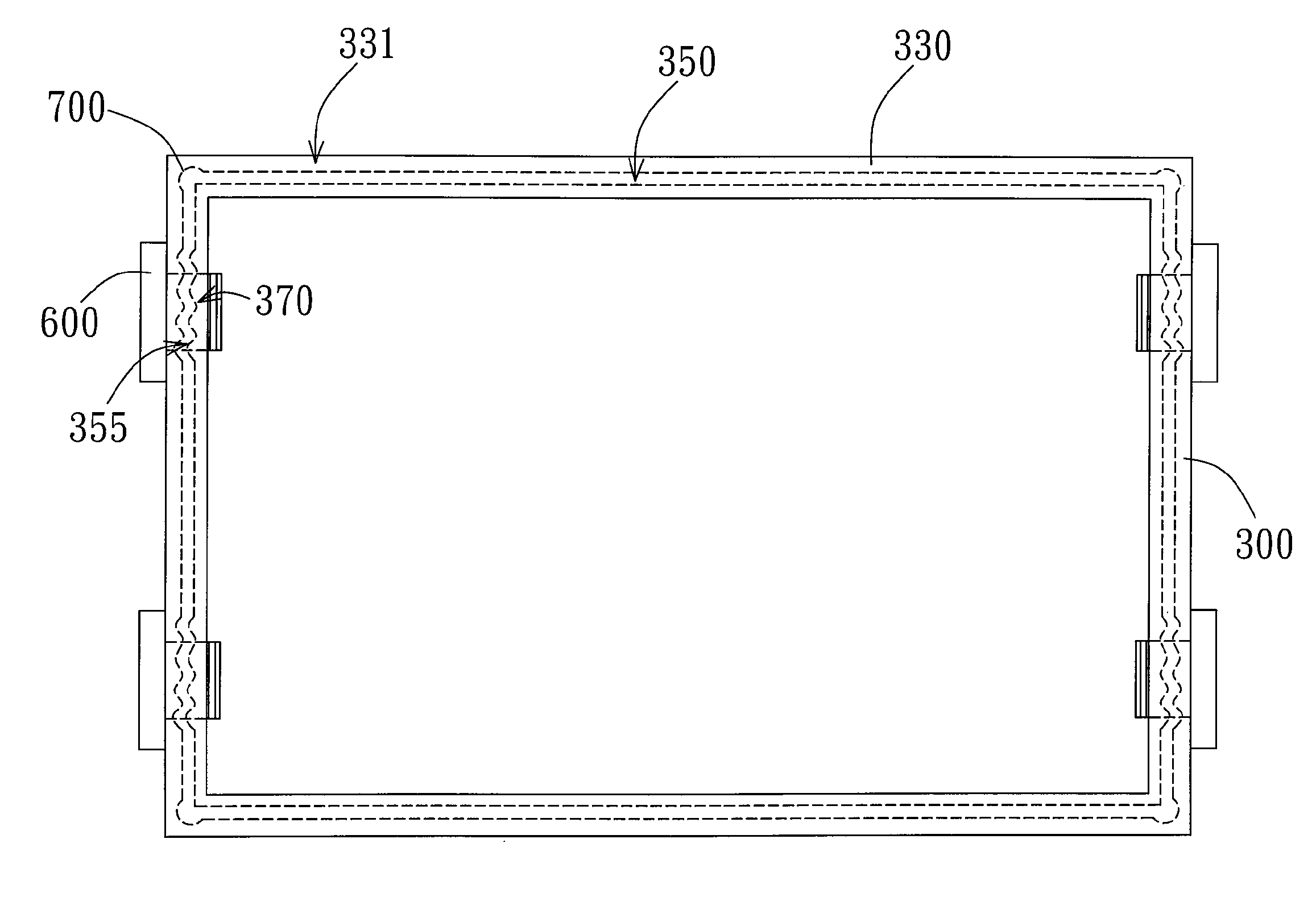
[0028]The present invention provides a display device, a front frame used by the display device and a manufacture method of the display device. The display device of the present invention includes LCD (Liquid Crystal Display) device, OLED (Organic Light Emitting Diode) display device and other types of multi-color or single-color display devices. The front frame partly covers a display panel of the display device. The material of the front frame can be metal, plastic and other organic or inorganic materials.

[0029]The display device of the present invention includes a display panel 100, a base 200 and a front frame 300, wherein the display panel 100 is disposed between the base 200 and the front frame 300. The display panel 100 in the embodiment shown in FIG. 2 is a transmissive LCD panel and the display device includes a backlight module 250 disposed between the display panel 100 and the base 200. However, in different embodiments, the display panels 100 can be transflective LCD pan...


PUM

PropertyMeasurementUnit
heightaaaaaaaaaa
widthaaaaaaaaaa
viscosityaaaaaaaaaa

Abstract

A display device, a front frame used therein, and a method of manufacture thereof are provided. The display device includes a display panel and the front frame. The display panel has a display surface which is partially covered by the front frame. The front frame includes a side wall corresponding to the sides of the display panel, a top plate extending from the side wall towards the center of the display panel, and cushion filler. The top plate has an inner surface featuring a groove distributed along the side wall. The cushion filler is contained within the groove while its top protrudes from the groove and contacts the display surface outside an active area.

Description

[0001]This application claims priority to Taiwan Application Serial Number 96114680, filed Apr. 25, 2007, which is herein incorporated by reference.BACKGROUND OF THE INVENTION[0002]1. Field of the Invention[0003]This invention relates to a display device, a front frame used therein, and a method of manufacture thereof.[0004]2. Description of the Prior Art[0005]Display panels such as LCD (Liquid Crystal Display) panels and OLED (Organic Light Emitting Diode) panel and display device using the display panel are becoming the mainstream in the field of display device. Products such as various types of display screens, home flat screen television, flat panel monitors of the personal computer and of the laptop, display screen of the mobile phone and the digital camera, use display panels as one of the essential components.[0006]FIG. 1a shows a conventional display device using display panel. As FIG. 1a shows, the display device includes a display panel 10, an outer frame 30, a back light ...

Claims


Application Information

Patent Timeline
Patent Type & Authority Patents(United States)
IPC IPC(8): G02F1/1333
CPCH05K5/02Y10T29/49993
Inventor HUANG, HSIN-TAOFANG, HSIU-MEI
Owner AU OPTRONICS CORP
Learn More