
Face feature point detection apparatus and feature point detection apparatus

a technology of feature point detection and detection apparatus, which is applied in the field of face feature point detection apparatus and feature point detection apparatus, can solve the problems of increasing computation time, hardly maintaining processing accuracy, and increasing computation time in the conventional way, and achieves the effect of high speed

Active Publication Date: 2011-05-03
ORMON CORP
View PDF14 Cites 11 Cited by
  • Summary
  • Abstract
  • Description
  • Claims
  • Application Information

AI Technical Summary

Benefits of technology

The invention proposes a face feature point detection apparatus that does not require shape correction processing and has improved processing speed. The apparatus uses a learning process to obtain correlation information between the feature points and the positions of the nodes in the image. This correlation information is then used to estimate the position of each feature point in the image. The apparatus also eliminates the need for high-density sampling and searching processing around each node, reducing the computation required. The apparatus can be used in driver monitoring systems and other applications where high-speed response is required.

Problems solved by technology

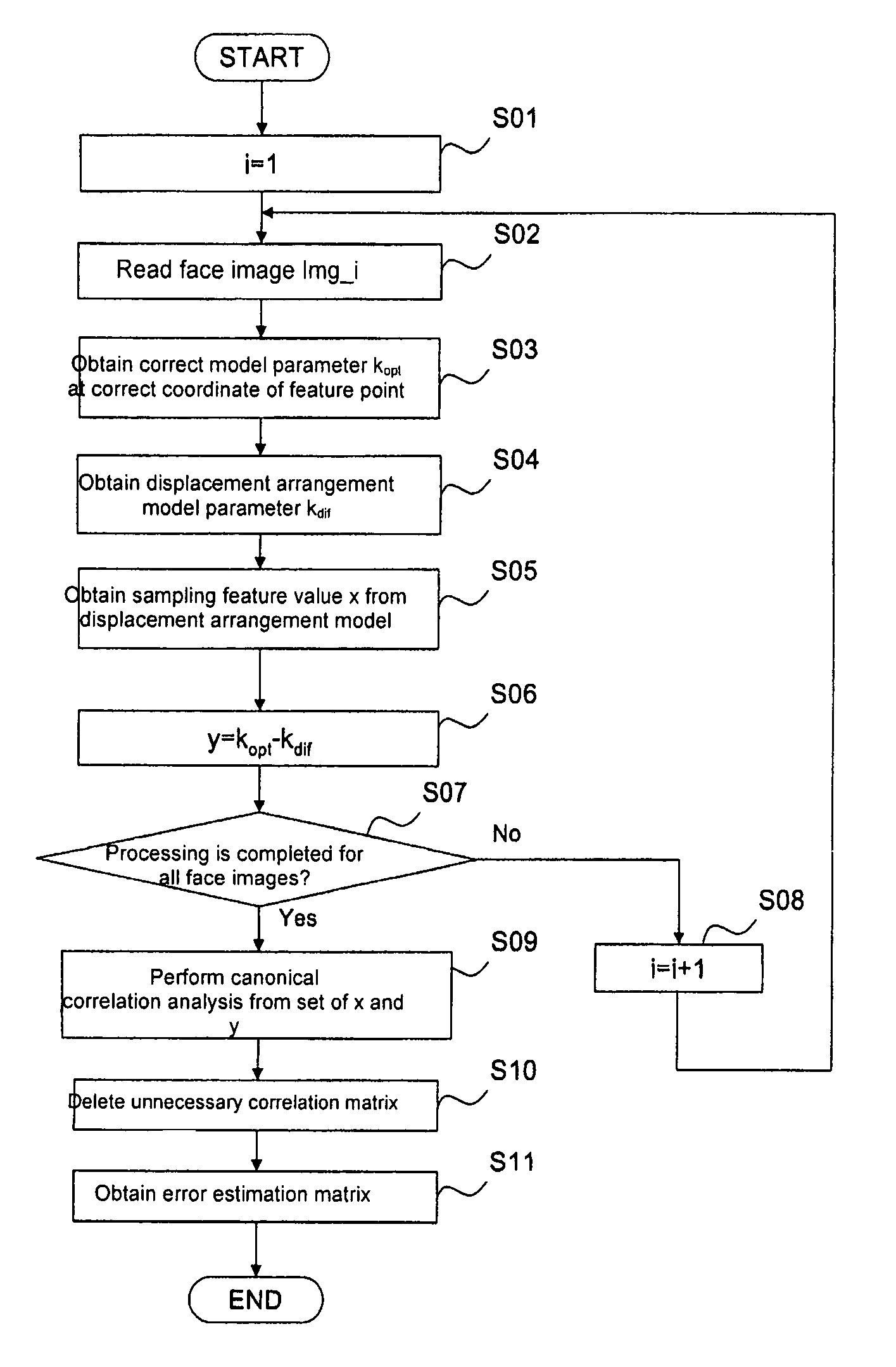
However, when a cause of the increase in computation time is studied in the conventional AAM, the required shape correction processing can be cited as the cause of the increase in computation time.
However, the homogeneous and high-density sampling can also be cited as one of the causes of the increase in computation time in the conventional AAM.
Therefore, when the sampling result is treated as a surface of the patch, the processing accuracy is hardly maintained unless the deformation associated with the movement of the node based on the result of the error estimation is corrected by the shape correction processing.

Method used


Image

  • Face feature point detection apparatus and feature point detection apparatus
  • Face feature point detection apparatus and feature point detection apparatus
  • Face feature point detection apparatus and feature point detection apparatus

Examples


operation example

[0138]FIG. 7 is a flowchart showing an operation example of the face feature point detection apparatus 1. An operation example of the face feature point detection apparatus 1 will be described below with reference to FIG. 7. The face feature point detection apparatus 1 reads the image which becomes the processing target through the image input unit 2 (S12). The face detection unit 3 detects the human face from the image which becomes the processing target. Then, the feature value obtaining unit 4 arranges the face shape model based on the initial parameter kinit at the initial position which is obtained according to the result of the face detection processing performed by the face detection unit 3 (S13). Then, the feature value obtaining unit 4 defines the variable i to substitute 1 for i, and the feature value obtaining unit 4 defines ki to substitute the initial parameter kinit for ki (S14). On the basis of the retina structure, the feature value obtaining unit 4 obtains the sampl...


PUM


Abstract

Plural nodes are arranged at predetermined initial positions, and feature values at plural sampling points around each node are obtained as a node feature value of each corresponding node. An error estimator indicating displacement between the current position of each node and the position of corresponding feature point is obtained based on correlation information on a difference between the node feature value obtained in a state in which the plural nodes are arranged at correct positions of the corresponding feature points and the node feature value obtained in a state in which the plural nodes are arranged at wrong positions of the corresponding feature points in a learning image, correlation information on a difference between the correct position and the wrong position, and a node feature value of each node. The position of each feature point is estimated in an input image based on the error estimator and the current position of each node.

Description

BACKGROUND OF THE RELATED ART[0001]1. Field of the Invention[0002]The present invention relates to an effective technique applied to an apparatus, a method, and a program for detecting a feature point of a target object from an image.[0003]2. Description of the Related Art[0004]Conventionally, in a technique of detecting the feature point of a target object from an image, there is a technique of detecting the feature point of a face which is set to the target object. The background art in the case where the face is set to the target object will be described below.[0005]For example, information regarding whether the eyes of a person are opened or closed, a face attitude, a direction of a visual line, and an expression of the face can be estimated by obtaining a feature point position of the face from an image in which the person is photographed. A state of the person can be acknowledged in detail from the estimation result. The detailed acknowledgement of the state of the person can ...

Claims


Application Information

Patent Timeline
Patent Type & Authority Patents(United States)
IPC IPC(8): G06K9/00
CPCG06K9/00281G06T7/0046G06T2207/30201G06T7/75G06V40/171
Inventor KINOSHITA, KOICHI
Owner ORMON CORP
Learn More