
Bicycle hub that will not produce noise

a technology of hubs and bicycles, applied in the field of hubs, can solve the problems of danger to the rider and uncomfortable sensation of the rider, and achieve the effect of not producing noise and preventing the incursion of nois

Inactive Publication Date: 2011-05-10
CHOSEN
View PDF7 Cites 21 Cited by
  • Summary
  • Abstract
  • Description
  • Claims
  • Application Information

AI Technical Summary

Benefits of technology

The primary objective of the present invention is to provide a bicycle hub that will not produce noise.
Another objective of the present invention is to provide a hub, wherein when the pedal is driven backward and the drive seat is rotatable backward, each of the pawl members is fully hidden in the respective receiving slot of the drive seat, and the locking detent of each of the pawl members is detached from the oneway ratchet teeth of the ratchet wheel constantly, so that each of the pawl members will not touch the ratchet wheel when the drive seat is rotatable backward to prevent from incurring a noise when the pedal is driven backward.
A further objective of the present invention is to provide a hub, wherein when the drive seat is rotatable backward, each of the pawl members is fully hidden in the respective receiving slot of the drive seat, and the locking detent of each of the pawl members is detached from the oneway ratchet teeth of the ratchet wheel constantly, so that the hub body is separated from the drive seat, and rotation of the hub body will not drive the drive seat and the pedal to prevent the pedal from being driven when the hub body is rotated backward.

Problems solved by technology

However, when each of the pawl members 53 passes by the one-way ratchet teeth 611 of the ratchet wheel 61 during the backward rotation of the drive seat 50, each of the pawl members 53 touches the oneway ratchet teeth 611 of the ratchet wheel 61 to produce noise due to the friction, thereby easily causing an uncomfortable sensation to the rider.
Thus, the pedal is driven by the drive seat 50 to rotate backward so that the rider is easily hit by the pedal, thereby causing danger to the rider.

Method used


Image

  • Bicycle hub that will not produce noise
  • Bicycle hub that will not produce noise
  • Bicycle hub that will not produce noise

Examples


Embodiment Construction

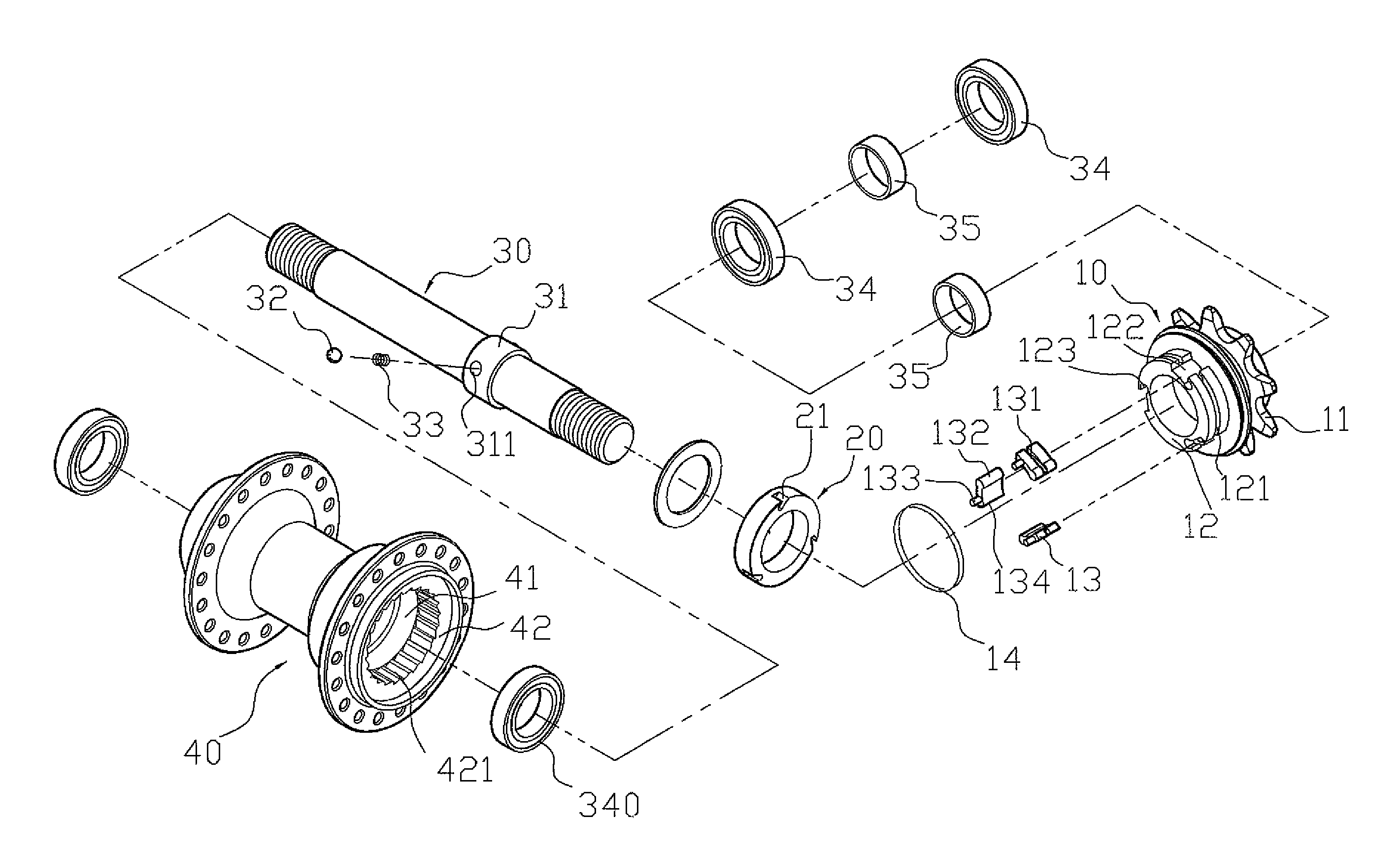
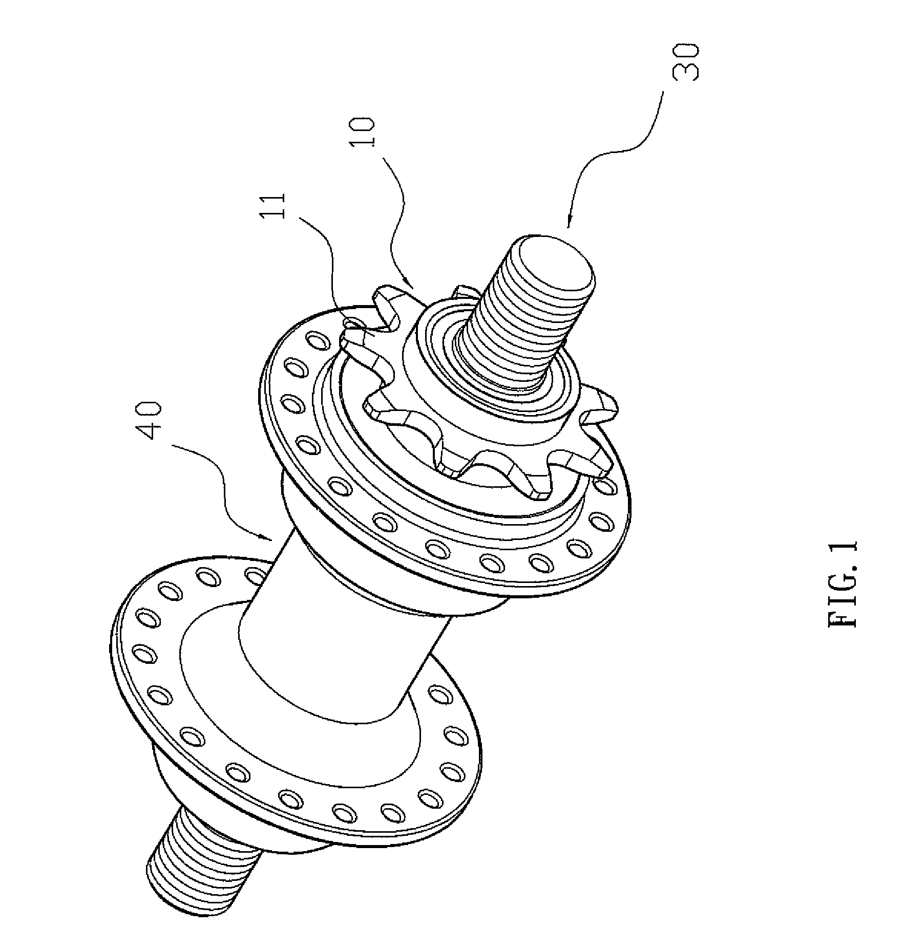
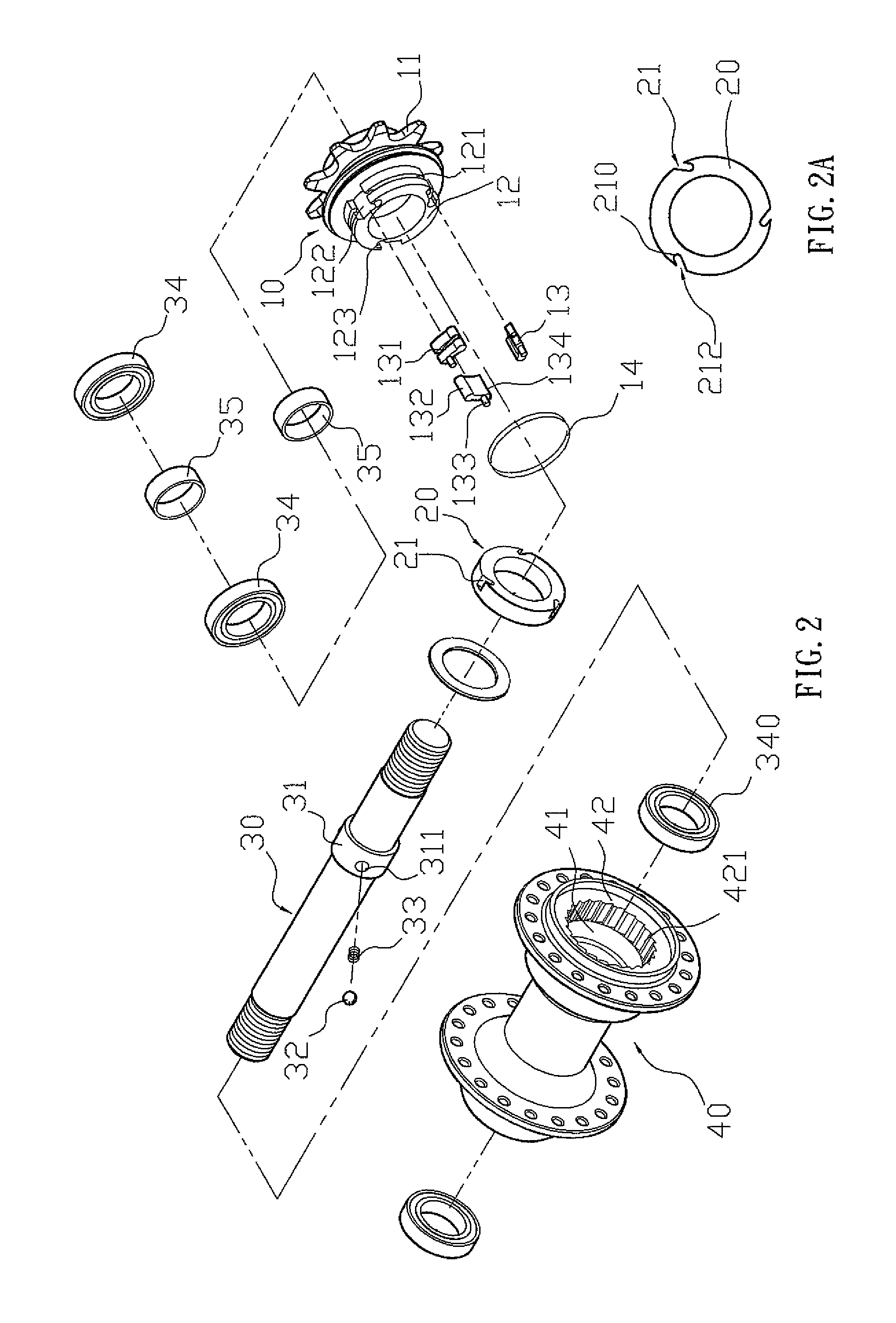
Referring to the drawings and initially to FIGS. 1-5, a hub for a bicycle in accordance with the preferred embodiment of the present invention comprises a shaft 30, a hub body 40 rotatably mounted on the shaft 30, a ratchet wheel 42 secured in the hub body 40 to drive the hub body 40 to rotate relative to the shaft 30 and having an inside provided with a plurality of oneway ratchet teeth 421, a damper 20 mounted between the shaft 30 and the hub body 40 and having a periphery provided with a plurality of oblique guide slots 21, a drive seat 10 rotatably mounted on the shaft 30 and having a first end provided with a support base 12 which is rotatable in the ratchet wheel 42 and has a periphery provided with a plurality of receiving slots 122, and a plurality of pawl members 13 each pivotally mounted in a respective one of the receiving slots 122 of the support base 12 of the drive seat 10 and each having a side provided with a guide post 133 which is movable in a respective one of the...


PUM


Abstract

A hub for a bicycle includes a shaft, a hub body, a ratchet wheel, a damper, a drive seat, and a plurality of pawl members. Thus, when the drive seat is rotatable backward, the locking detent of each of the pawl members is detached from the oneway ratchet teeth of the ratchet wheel constantly, so that each of the pawl members will not touch the ratchet wheel to prevent from incurring a noise. In addition, when the drive seat is rotatable backward, the hub body is separated from the drive seat, and rotation of the hub body will not drive the drive seat and the pedal to prevent the pedal from being driven when the hub body is rotated backward.

Description

BACKGROUND OF THE INVENTION1. Field of the InventionThe present invention relates to a hub and, more particularly, to a hub for a bicycle.2. Description of the Related ArtA conventional hub for a bicycle in accordance with the prior art shown in FIGS. 8 and 9 comprises a shaft 70, a hub body 60 rotatably mounted on the shaft 70, a ratchet wheel 61 secured in the hub body 60 to drive the hub body 60 to rotate relative to the shaft 70 and having an inside provided with a plurality of one-way ratchet teeth 611, a drive seat 50 rotatably mounted on the shaft 70 and having a first end provided with a support base 52 which is rotatable in the ratchet wheel 61 and has a periphery provided with a plurality of receiving slots 521, a plurality of pawl members 53 each pivotally mounted in a respective one of the receiving slots 521 of the support base 52 of the drive seat 50 and each meshing with the oneway ratchet teeth 611 of the ratchet wheel 61 so that the ratchet wheel 61 is combined with...

Claims


Application Information

Patent Timeline
Patent Type & Authority Patents(United States)
IPC IPC(8): F16D41/30
CPCF16D41/30Y10T74/2135
Inventor CHEN, CHING-SHU
Owner CHOSEN
Learn More