Femoral compression device

a compression device and femoral technology, applied in the field of femoral compression devices, can solve problems such as complete unsuitability for the present application

Active Publication Date: 2011-05-10
ST JUDE MEDICAL COORDINATION CENT
View PDF25 Cites 26 Cited by
  • Summary
  • Abstract
  • Description
  • Claims
  • Application Information

AI Technical Summary

Benefits of technology

[0005]In the known femoral compression device, the pressure gauge comprises a mechanical manometer with an analog pointer. It can therefore be appreciated that the pressure measurement system is rather insensitive, i.e. small pressure changes will not be registered by the analog pointer due to friction and the inherent inertia of the mechanical components of the manometer. This means, for example, that the manometer is not capable of indicating when the blood flow through a femoral artery has been cut off, something which ideally should be possible to note by observing the discontinuation of small regular pressure variations inside the air cushion, the pressure variations being induced by the systolic pulses in the femoral artery over which the air cushion has been positioned. By observing the ceasing of systolic pulses, the pressure applied to the femoral artery could be fine-tuned to the medical condition of the patient who is undergoing the medical treatment in question, i.e. application of an excessive amount of pressure could be avoided, which spares the patient from discomfort and expedites the time of treatment.
[0009]An electronic manometer does further provide for possibilities regarding how the measured pressure is displayed for a user. The output pressure values can, for example, be averaged values over a certain time interval to filter out artefacts induced by the patient's movements, i.e. a damping can easily be incorporated in the system.

Problems solved by technology

As is normal in the art, these blood pressure monitors are not sealed air-tight systems but slowly leaking systems, and are as such completely unsuited for the present application, as will be understood from the description below.

Method used


Image

  • Femoral compression device
  • Femoral compression device
  • Femoral compression device

Examples


Embodiment Construction

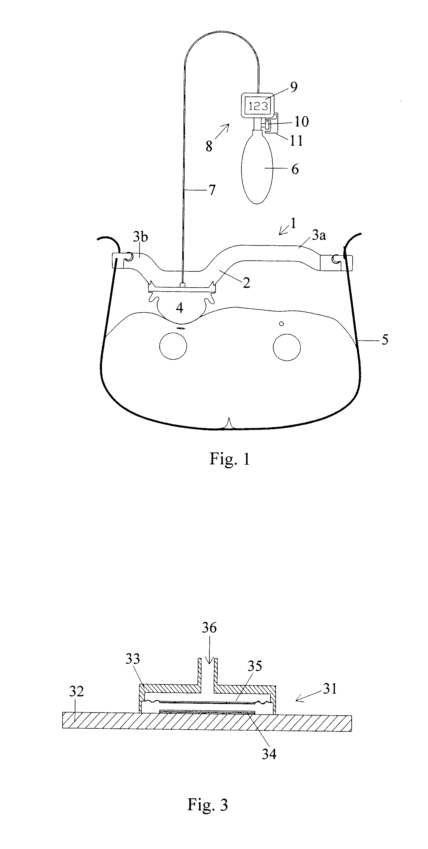
[0016]In FIG. 1, a femoral compression device 1 is schematically illustrated. The femoral compression device 1 comprises a base plate 2 with two extensions 3a and 3b, an inflatable air cushion 4, a belt 5, a pump 6, an air connection 7, and an electronic pressure gauge or manometer 8 with a display 9. Except for the manometer 8 and possibly the pump 6, the femoral compression device 1 is of the same construction as was disclosed in the previously mentioned patents U.S. Pat. No. 5,307,811 and EP 0 462 088. In use, the inflatable and semi-spherical air cushion 4 is positioned over the femoral artery of a patient, and the belt 5, which extends from the end of the first extension 3a, around the patient's body and to the end of the second extension 3b, is tightened and secured by belt fasteners at the end of each extension. To apply pressure on the femoral artery, the inflatable semi-spherical air cushion 4 is inflated by the pump 6 to a certain pressure, which is measured by the manomet...


PUM


Abstract

A femoral compression device (1) for compressive bearing against the femoral artery of a patient, comprising a base plate (2), an inflatable air cushion (4), and an electronic manometer (8) connected to the inflatable air cushion for measurement of the current pressure difference between the pressure prevailing inside the inflatable air cushion and the ambient air pressure. The femoral compression device can further comprise a mechanical device (11; 46) which prevents an air opening leading to the inflatable air cushion from being closed before the manometer is zeroed. In another embodiment, an electronic manometer is provided such that a current characteristic of an electric signal representing the current pressure difference can be compared with a corresponding characteristic which was obtained at zero pressure difference and which was stored in the electronic manometer, wherein the manometer cannot be zeroed as long as the current characteristic deviates more than a predetermined amount from the stored characteristic.

Description

FIELD OF THE INVENTION[0001]The invention relates generally to a femoral compression device, and in particular to a femoral compression device comprising an electronic pressure gauge.BACKGROUND OF THE INVENTION[0002]Femoral compression devices for applying pressure on a patient's femoral artery after completion of an interventional procedure are known. An example of such a femoral compression device is disclosed in the patents U.S. Pat. No. 5,307,811 and EP 0 462 088, which are assigned to the present assignee. The entire contents of these documents are incorporated herein by reference for the devices, methods, and techniques disclosed therein.[0003]A femoral compression device according to these publications comprises basically a pressurizing means for compressive bearing against a puncture site at a femoral artery of a patient, a belt adapted to be fixed around the patient's body, and a base plate supporting the pressurizing means and being provided with two extensions. In use, th...

Claims


Application Information

Patent Timeline
Patent Type & Authority Patents(United States)
IPC IPC(8): A61B17/00
CPCA61B17/135A61B2017/00123A61B2017/00115
Inventor ANG.KERFELDT, DANSMITH, LEIFLINDSTROM, MARIEADENMARK, TOBIAS
Owner ST JUDE MEDICAL COORDINATION CENT
Why Eureka
Try Eureka