Wastewater treatment and dispersal system

a technology of dispersal system and wastewater treatment, which is applied in the direction of sewage draining, liquid displacement, separation process, etc., can solve the problems of affecting the growth of biomats, and the end of the drainfield failure, so as to maximize the amount of air/oxygen, prolong the treatment time, and reduce the effect of was

Inactive Publication Date: 2007-12-18
BRANZ STEVEN A
View PDF39 Cites 6 Cited by
  • Summary
  • Abstract
  • Description
  • Claims
  • Application Information

AI Technical Summary

Benefits of technology

[0008]The present invention is directed to a simple and economical wastewater treatment and dispersal system that addresses the problems described above. That is, the treatment and dispersal system is of the type used in conjunction with a septic tank and is directed at lengthening the time of treatment, maximizing the amount of air / oxygen in contact with the wastewater, or a combination thereof, in the dispersal field to minimize BOD and TSS.
[0013]In one embodiment, the conduits of the present invention each have at least one discharge opening that is so positioned to ensure that there will be wastewater standing in a about one half of the volume of each of the conduits. Depending upon whether the system is configured to lengthen the time of treatment or maximize the amount of air / oxygen in contact with the wastewater, or both, the one or more discharge openings may be formed in the upper portion of the conduit or may be formed in a cap, or the like, at the end of the conduit, or a combination thereof. With discharge openings formed in this way, the retention time of the wastewater within the system is maximized, while maximizing the exposure of the wastewater to air, either ambient or forced. Where the one or more discharge openings are formed in the upper portion of the conduit itself, the wastewater eventually rises until it seeps out the discharge openings. Where the one or more discharge openings are formed in an end cap, or flange, the wastewater must travel the full length of the conduit before seeping out, which also maximizes the retention time within the system.
[0014]In a second embodiment, using the same or similar conduits, the treatment and dispersal system of the present invention uses forced air through the wastewater itself. Desirably, a pump or fan creates the forced air flow. The flow of air, at a prescribed flow rate, ensures maximum activation, and some agitation, of the wastewater and maximum contact between the wastewater and air. Accordingly, biochemical activity is enhanced with a corresponding reduction in BOD and TSS.
[0016]As those skilled in the art will appreciate, there is no technical or scientific reason why dispersal fields for septic systems must comprise multiple, parallel conduits. Rather, in recognition of limited land space for the practical installation of a wastewater treatment and dispersal system, there is a need to create flow pathways that maximize the dispersal field length, but limit the area required for installation. Accordingly, it has been found that a wastewater dispersal system can be constructed as a single conduit system. Further, it has been found that the conventional gravel-type drainage fields may be reduced or eliminated with the single conduit system.
[0018]In another embodiment, the wastewater dispersal system for a gravel-less wastewater treatment system comprises an inner conduit and a water permeable outer cover surrounding the inner conduit. The conduit is similar to the inner conduit of the previous embodiments. The water permeable outer cover that surrounds the inner conduit eliminates the need for the gravel drainage trenches and reduces the size of the dispersal field conduit configuration. Further, the dispersal system comprise a geotextile draining material that is wrapped around the inner conduit to facilitate the passage of wastewater, but the retention of solids.

Problems solved by technology

The waste products of human activity take many forms, and present numerous disposal and sanitation issues.
The biomat, or growth layer of organic matter, accumulates over a period of time and eventually leads to ultimate failure of the drainfield.
Thus, measures which reduce BOD and TSS lead to slower growth of the biomat, and thus prolonged life of the septic system.
While these principles work well for surface treatment systems, commonly known as activated sludge processes, there has not been a satisfactory and reliable solution for septic systems.
There are known septic dispersal systems that incorporate standpipes, or vents, to provide for some natural circulation of air through the dispersal field, but these systems have had little practical effect in reducing the BOD and / or TSS of the waste stream.

Method used


Image

  • Wastewater treatment and dispersal system
  • Wastewater treatment and dispersal system
  • Wastewater treatment and dispersal system

Examples


Embodiment Construction

[0038]The present invention is directed to a wastewater treatment system aimed at addressing the problems described above. The present invention is best understood by first summarizing the prior art and current wastewater treatment systems.

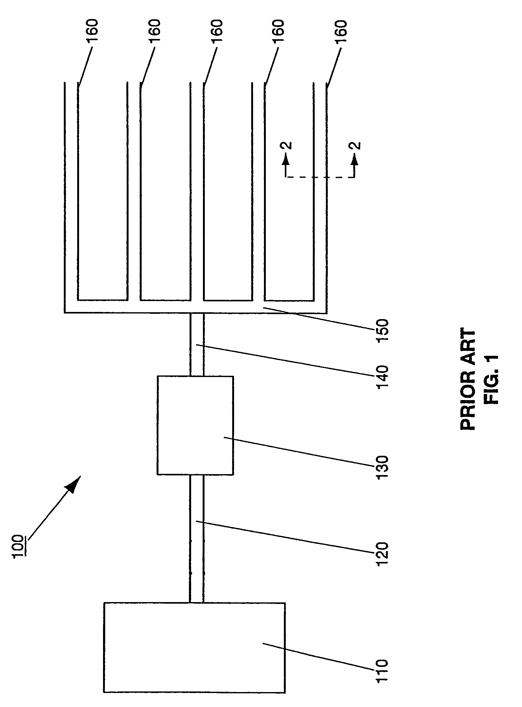
[0039]Referring first to FIG. 1, a conventional residential wastewater, or septic, system is shown generally a 100. Wastewater, comprising liquids and suspended solids, originates from a residential structure 110, for example, by flowing from sinks, tubs, toilets, etc. At least one septic inlet header 120 directs the wastewater to a septic tank 130. Septic tanks are well known in the art and are generally formed of concrete or steel and have capacities averaging 1000 gallons for a single residence. Within the septic tank 130, the wastewater is deposited, where the separation and organic digestion of the waste begins. Solid matter which floats generally forms a “scum” layer on the surface, non-floatable solids settle to form a “sludge” layer on the...


PUM

PropertyMeasurementUnit
diameteraaaaaaaaaa
diameteraaaaaaaaaa
diameteraaaaaaaaaa

Abstract

A wastewater treatment and dispersal system wherein wastewater will stand until it has a BOD of less than about 125 mg / l. The dispersal field may comprise inner and outer conduits, an inner conduit and a permeable outer cover, or a trough and an enclosure.

Description

RELATED APPLICATIONS[0001]This application is filed pursuant to 37 C.F.R. § 1.53(b) and is a Divisional of application Ser. No. 10 / 931,900, filed Sep. 1, 2004 now U.S. Pat. No. 7,118,669, which is a Continuation-in-Part of application Ser. No. 10 / 132,496, filed Apr. 25, 2002, now U.S. Pat. No. 6,821,424.FIELD OF THE INVENTION[0002]The present invention relates to wastewater treatment, and particularly to wastewater treatment systems for onsite applications.BACKGROUND OF THE INVENTION[0003]The disposal and / or treatment of waste is as old as civilization itself. The waste products of human activity take many forms, and present numerous disposal and sanitation issues. Of particular importance in the last half century has been the preservation and conservation of our natural resources, including groundwater and land, in particular.[0004]The treatment of wastewater is not a new art, and involves essentially three broad aspects: conveyance, treatment, and disposal. Conveyance is more ofte...

Claims


Application Information

Patent Timeline
Patent Type & Authority Patents(United States)
IPC IPC(8): C02F3/30
CPCC02F3/046E03F1/002C02F3/288Y02W10/10
Inventor BRANZ, STEVEN A.
Owner BRANZ STEVEN A
Why Eureka
Try Eureka