Duplexer

a duplexer and dual-band technology, applied in the field of duplexers, can solve the problems of difficult to improve the attenuation characteristic of the opposite passband in the duplexer, and difficult to reduce the size of the portable terminal device or the thickness, so as to improve the attenuation characteristics of the opposite passband. the effect of improving the attenuation characteristics of the opposite passband

Active Publication Date: 2011-05-10
TAIYO YUDEN KK
View PDF18 Cites 47 Cited by
  • Summary
  • Abstract
  • Description
  • Claims
  • Application Information

AI Technical Summary

Benefits of technology

[0014]The present invention has been made in view of the above circumstances and provides a duplexer that can improve the attenuation characteristics of opposite passbands.
[0015]According to one aspect of the present invention, there is provided a duplexer including: a transmit filter of a ladder type filter, connected between a common terminal and a transmitting terminal; and a receive filter of the ladder type filter, connected between the common terminal and a receiving terminal, and one or more parallel resonators in the transmit filter are grounded through a transmitting inductance; and a portion of multiple parallel resonators are grounded through a first receiving inductance and a remaining portion of the multiple parallel resonators are grounded through a second receiving inductance. The attenuation characteristics of opposite passbands can be improved.

Problems solved by technology

The dielectric duplexer has a large size, making it difficult to reduce the size of the portable terminal device or to reduce the thickness thereof.
Even when the surface acoustic wave device is used for one of the transmit filter and the receive filter, the size of the dielectric device makes it difficult to reduce the size of the portable terminal device or to reduce the thickness thereof.
In particular, it is difficult to improve the attenuation characteristic of the opposite passband in the duplexer for use in the W-CDMA system operating at 2 GHz.

Method used


Image

  • Duplexer
  • Duplexer
  • Duplexer

Examples


first exemplary embodiment

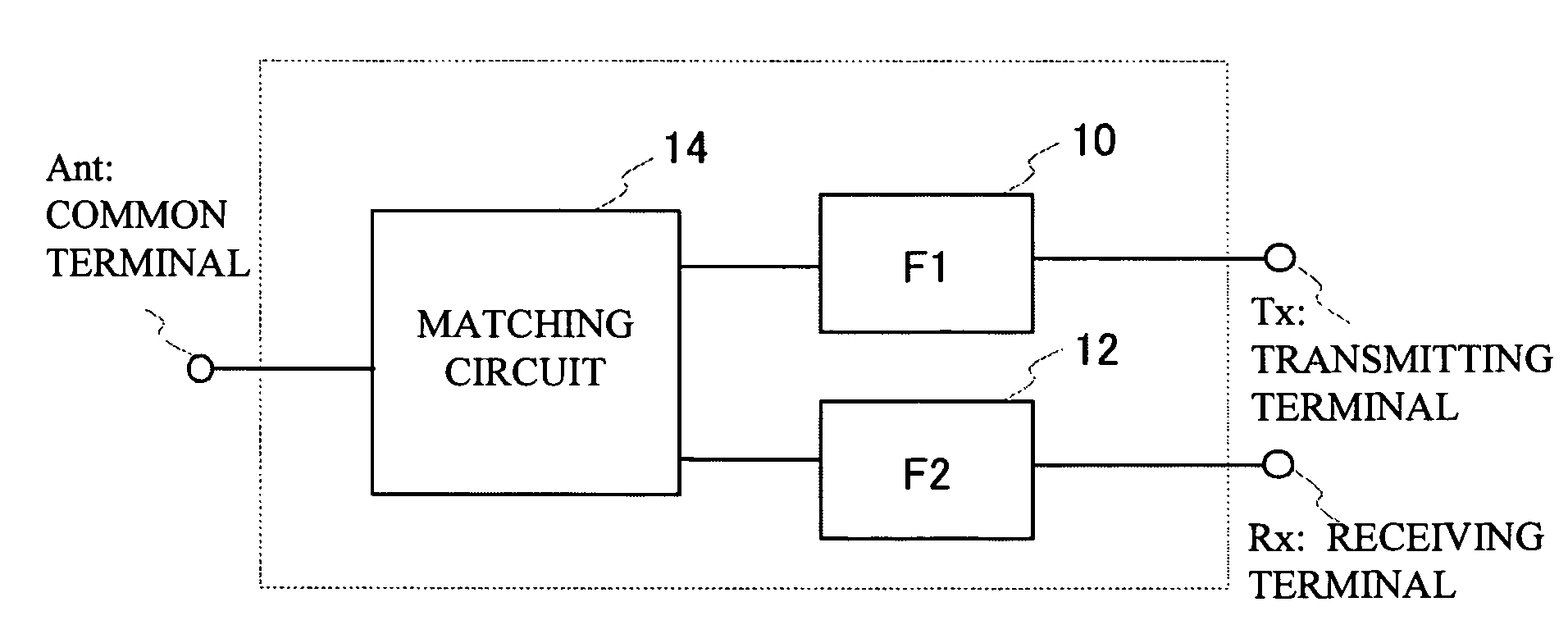
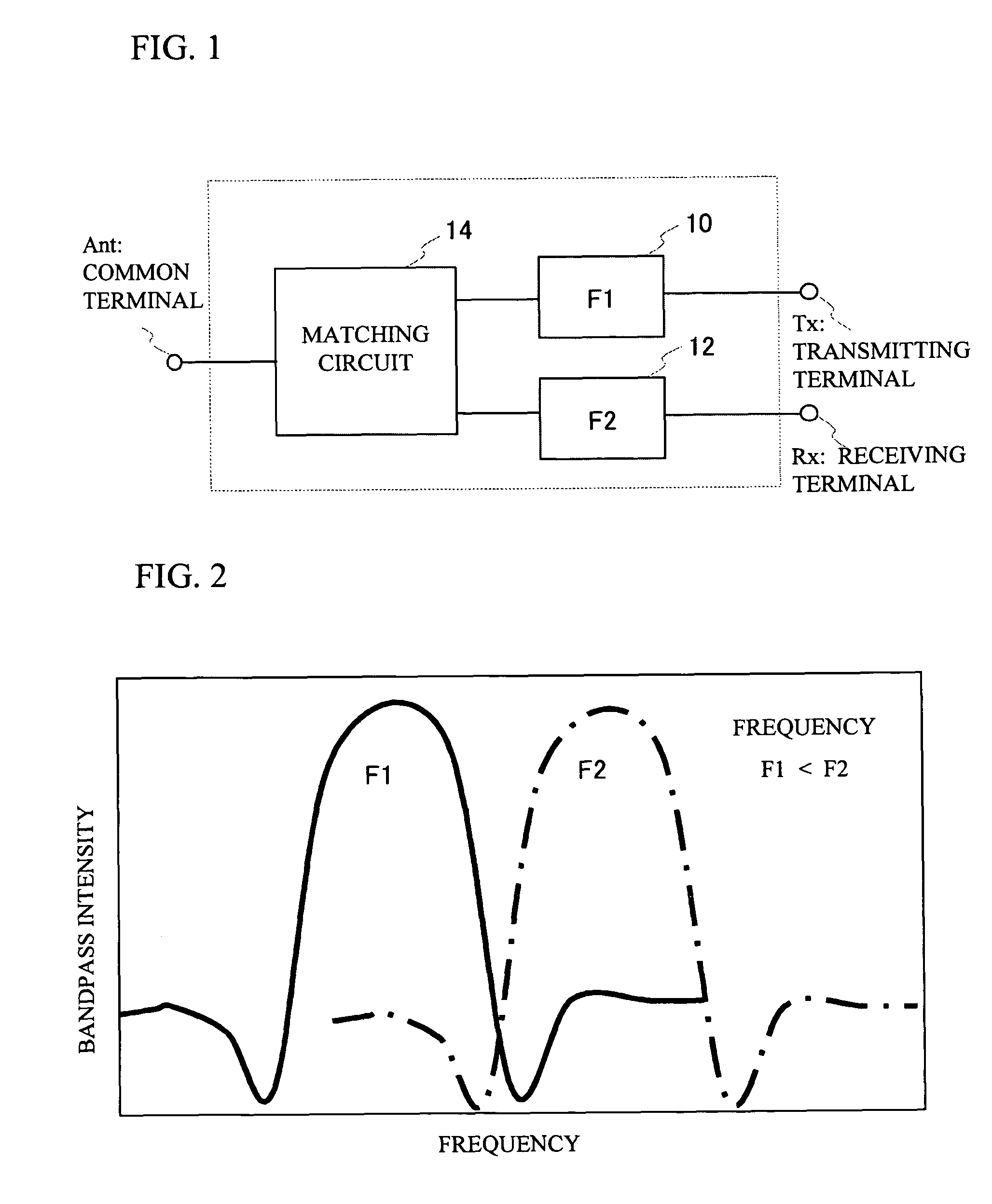
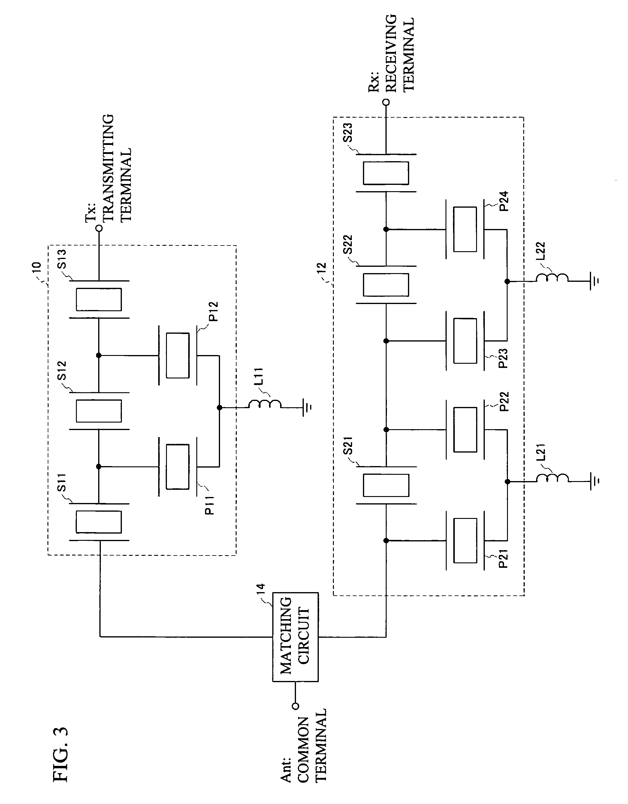
[0054]A first exemplary embodiment of the present invention is an example in which a duplexer having ladder type filters for use in a W-CDMA system operating at 2 GHz is mounted on a stacked package. FIG. 3 is a circuit diagram of the duplexer employed in the first exemplary embodiment of the present invention. There are provided: the transmit filter 10 of a ladder type filter connected between the common terminal Ant and the transmitting terminal Tx; and the receive filter 12 of the ladder type filter connected between the common terminal Ant and the receiving terminal Rx. The matching circuit 14 is connected between the common terminal Ant and the transmit filter 10 and the receive filter 12.

[0055]The transmit filter 10 is a ladder type filer having series resonators S11 through S13 and parallel resonators P11 and P12. All the parallel resonators P11 and P12 in the transmit filter 10 are connected together at the sides of the ground terminals, and are grounded through a transmitti...

second exemplary embodiment

[0074]FIG. 10A through FIG. 10C respectively show the die attach layer 26, the line pattern layer 28, and the line pattern / footpad layer 30 in the duplexer of a comparative example 2. FIG. 10D through FIG. 10F respectively show the die attach layer 26, the line pattern layer 28, and the line pattern / footpad layer 30 in the duplexer employed in a second exemplary embodiment of the present invention. In the duplexer of the comparative example 2, the second receiving ground line pattern RG2L, the first receiving ground line pattern RG1L, and the transmitting ground line pattern TGL are provided on the same line pattern / footpad layer 30. Meanwhile, in the duplexer employed in the second exemplary embodiment, the second receiving ground line pattern RG2L is provided on the line pattern layer 28. In other words, the second receiving ground line pattern RG2L is provided on a different layer from the first receiving ground line pattern RG1L. In the second exemplary embodiment and the compar...

third exemplary embodiment

[0076]FIG. 12A shows the footpad layer 32 in the duplexer of comparative example 3, in which the ceramic coat is not shown. FIG. 12B shows the footpad layer 32 in the duplexer employed in the first exemplary embodiment of the present invention, in which the ceramic coat is not shown. Referring to FIG. 12B, in the duplexer employed in the first exemplary embodiment, the ground footpad GndFP1 is electrically separated and isolated from the ground footpad GndFP2, the ground footpad GndFP1 being coupled to the first receiving ground line pattern RG1L, which is the line pattern coupled to the parallel resonators P21 and P22 at the side of the common terminal Ant of the receive filter 12, the ground footpad GndFP2 being coupled to the second receiving ground line pattern RG2L and the transmitting ground line pattern TGL. Meanwhile, referring now to FIG. 12A, in the duplexer of a comparative example 3, the transmitting ground line pattern TGL, the first receiving ground line pattern RG1L, ...


PUM


Abstract

A duplexer includes a transmit filter of a ladder type filter, connected between a common terminal and a transmitting terminal, and a receive filter of the ladder type filter, connected between the common terminal and a receiving terminal. One or more parallel resonators in the transmit filter are grounded through a transmitting inductance, and a portion of multiple parallel resonators are grounded through a first receiving inductance and a remaining portion of the multiple parallel resonators are grounded through a second receiving inductance.

Description

BACKGROUND OF THE INVENTION[0001]1. Field of the Invention[0002]This invention generally relates to duplexers, and more particularly, to a duplexer in which ladder type filters are for use in a transmit filter and a receive filter.[0003]2. Description of the Related Art[0004]In recent years, with the advancement of mobile communications systems, portable information terminals or the like are rapidly wide spreading. Developments have been done to reduce the sizes of the above-described terminals and to improve performance thereof. Both analogue and digital are used for mobile telephone systems, in which 800 MHz to 1 GHz frequency bandwidth and 1.5 GHz to 2.0 GHz frequency bandwidth are mainly used. There have been proposed antenna duplexers that employ a surface acoustic wave filter or piezoelectric thin-film resonator filter so as to be employed in the devices for mobile communications systems.[0005]In the development of the mobile telephones these days, the performance of the termi...

Claims


Application Information

Patent Timeline
Patent Type & Authority Patents(United States)
IPC IPC(8): H04B1/44H03H9/02H03H9/17H03H9/25H03H9/58H03H9/70H03H9/72
CPCH03H9/0571H03H9/0576H03H9/725H03H9/72H03H9/706H03H9/54
Inventor IWAMOTO, YASUHIDETSUTSUMI, JUNIWAKI, MASAFUMIUEDA, MASANORI
Owner TAIYO YUDEN KK
Why Eureka
Try Eureka