RF circuit with control unit to reduce signal power under appropriate conditions

a control unit and signal power technology, applied in the field of radio frequency (rf) circuits, can solve the problems of signal characteristics that fail to meet certain specified requirements, linear operation of power amplifiers may degrade simultaneously, and signal purity that begins to degrad

Active Publication Date: 2011-05-10
NXP USA INC
View PDF20 Cites 49 Cited by
  • Summary
  • Abstract
  • Description
  • Claims
  • Application Information

AI Technical Summary

Problems solved by technology

When signal compression occurs, the spectral purity of the signal begins to degrade and the linear operation of the power amplifier may degrade simultaneously.
Even marginally non-linear power amplifiers may produce signals having characteristics that fail to meet certain specified requirements.

Method used


Image

  • RF circuit with control unit to reduce signal power under appropriate conditions
  • RF circuit with control unit to reduce signal power under appropriate conditions
  • RF circuit with control unit to reduce signal power under appropriate conditions

Examples


Embodiment Construction

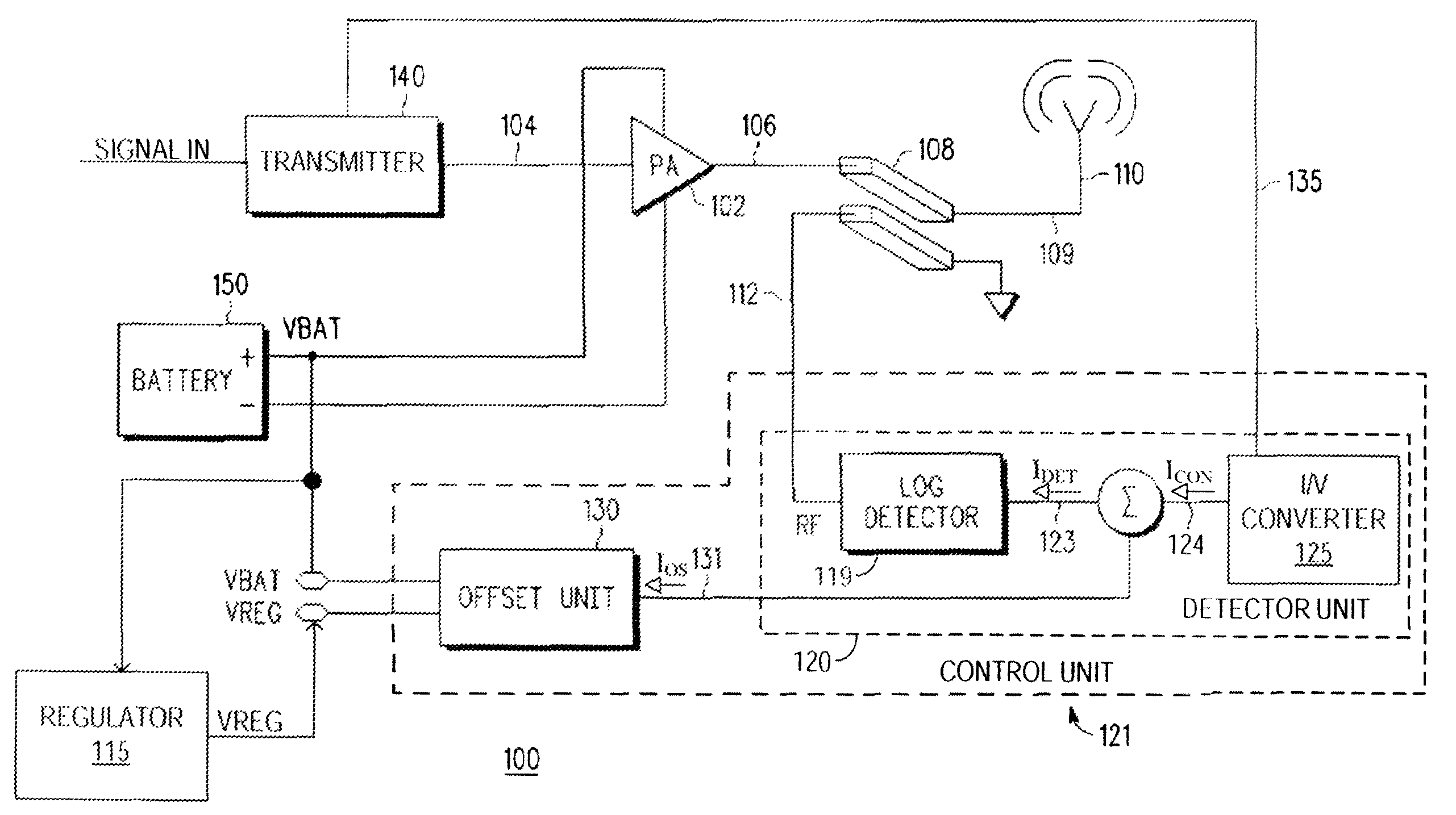
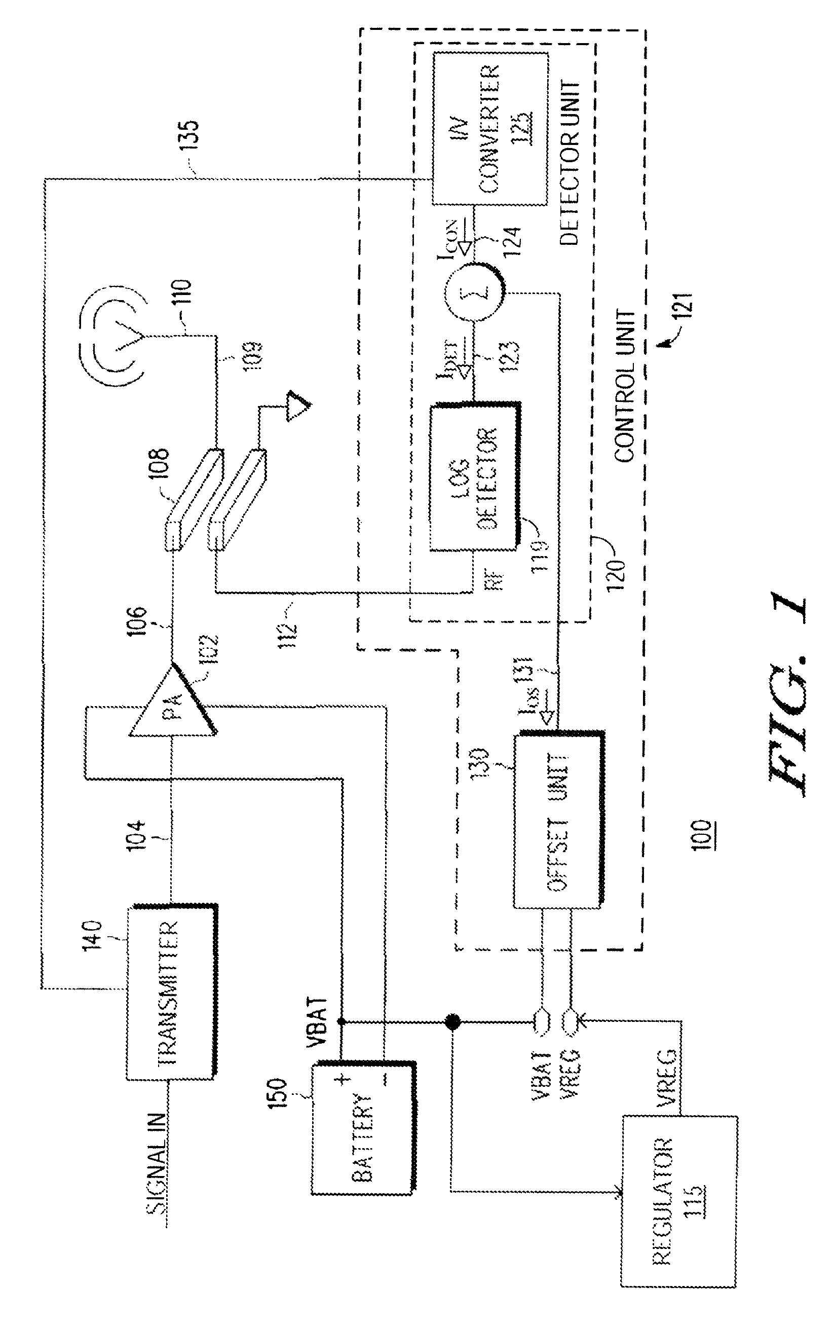
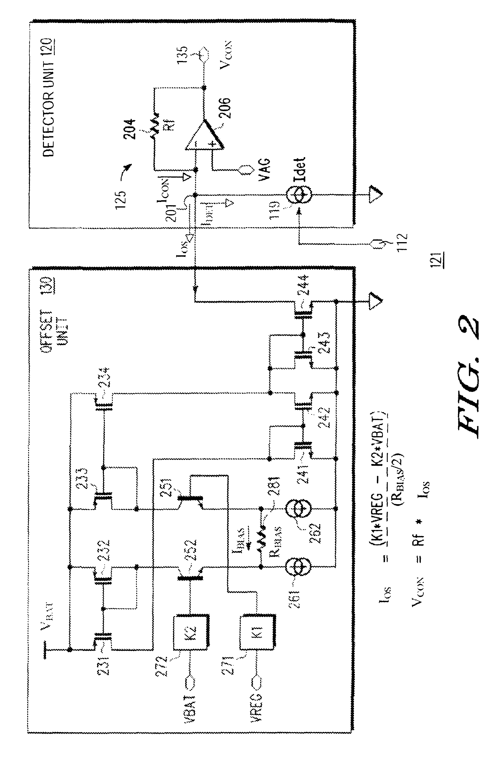
In one aspect, a disclosed RF circuit is operable to be powered by a supply voltage. The supply voltage may be provided by a battery that outputs a battery voltage. In some implementations, the battery voltage is applied to the RF circuit so that the supply voltage equals the battery voltage. The RF circuit includes a power amplifier that is powered by the supply voltage The power amplifier receives an RF input signal and produces an RF output signal. The RF circuit further includes a detector that generates a detector output signal. The detector output signal is indicative of the RF output signal power. An offset unit adjusts the detector output signal when a low battery voltage condition is encountered. The low battery voltage condition occurs when the supply voltage is below a specified threshold. In this manner, the RF output signal power is controlled at least in part by the adjusted detector signal. Moreover, because the adjusted detector output signal is influenced by the RF ...


PUM


Abstract

A disclosed RF circuit includes a power amplifier that produces an RF output signal, a detector to generate a detector signal indicative of a power of the RF output signal, and an offset unit to produce an offset signal that indicates low supply voltage conditions. The power of the RF output signal is reduced, at least in part, by a control signal reflecting a combination of the detector signal and the offset signal. The circuit may include a transmitter to provide an RF input signal to the power amplifier. The transmitter may receive the control signal and adjust a power of the RF input signal based on the control signal. The detector may produce a control current indicative of the RF output signal power. The offset unit produces the offset signal based on a difference between the supply voltage and a nominal supply voltage value.

Description

BACKGROUND1. FieldThe disclosed subject matter is in the field of radio frequency (RF) circuits and, more particularly, battery-powered RF circuits for use in applications requiring linear power amplifier performance.2. Related ArtRF circuits are prevalent in a larger number of applications including wireless or mobile telecommunications where one or more rechargeable batteries frequently provide the source of power for the RF circuit. RF circuits are well known to include transmitter units that produce an RF signal that is provided as an input to a power amplifier. The power amplifier amplifies and / or modulates the received signal to generate an RF output signal that is converted into electromagnetic waves and propagated into space via an antenna. Generally, a battery powered RF device includes a voltage regulator or power supply circuit that receives the voltage produced by the battery as its input and generates one or more supply voltages and / or reference voltages for the RF circ...

Claims


Application Information

Patent Timeline
Patent Type & Authority Patents(United States)
IPC IPC(8): H04B1/04H01Q11/12
CPCH04B1/1607H04B1/04
Inventor GONZALEZ, DAVID M.
Owner NXP USA INC
Why Eureka
Try Eureka