PLC

a logic controller and programming technology, applied in the field of plc, can solve the problems of not being edited or even seen, requiring considerable knowledge and labor, and not being able to meet the needs of users, so as to facilitate user understanding and edition.

Inactive Publication Date: 2011-05-10
JTEKT CORP
View PDF11 Cites 7 Cited by
  • Summary
  • Abstract
  • Description
  • Claims
  • Application Information

AI Technical Summary

Benefits of technology

[0033]Meanwhile, in the PLC according to this invention, it is preferable that the graphical language is a ladder diagram, a function block diagram, a structured text or an instruction list. These languages are frequently employed in the PLC, thereby facilitating the user's understanding and edition.

Problems solved by technology

Namely, in order that the user creates the execution program, considerable knowledge and labor are required.
Thus, a longer time and higher production cost have been needed as compared with the case of creating a general execution program.
However, in the above PLC, the execution program automatically created was black-boxed so that it could not be edited or even seen.
Namely, since the execution program automatically created cannot be edited, there are fears of generating the problems such as making wiring troublesome, an increase in a device establishing space, cost increase, etc.

Method used


Image

  • PLC
  • PLC
  • PLC

Examples


Embodiment Construction

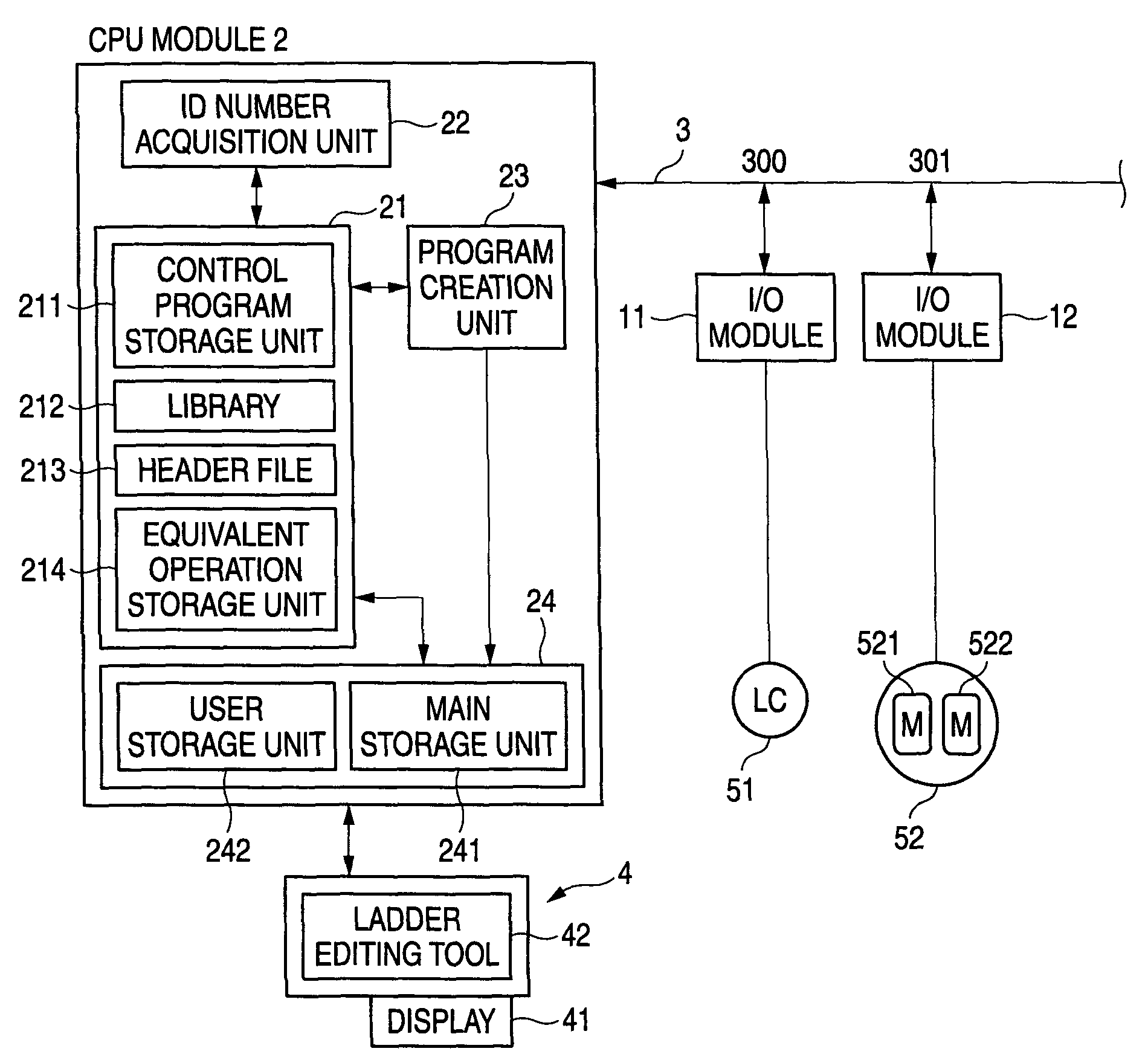
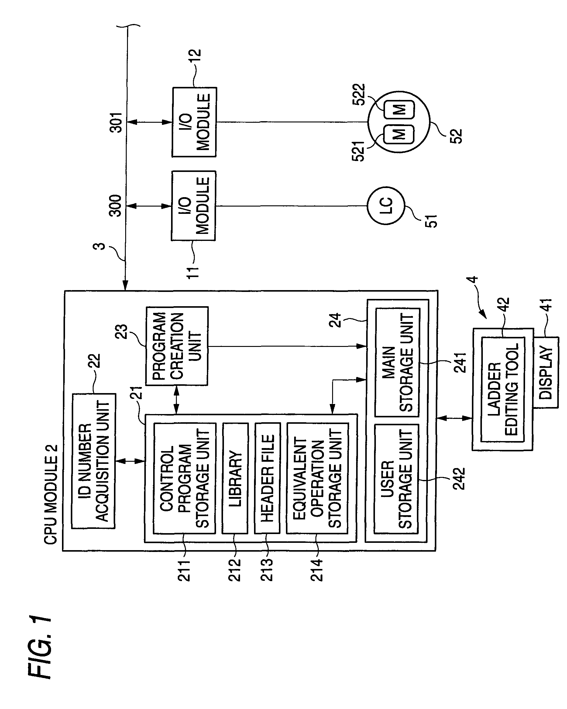
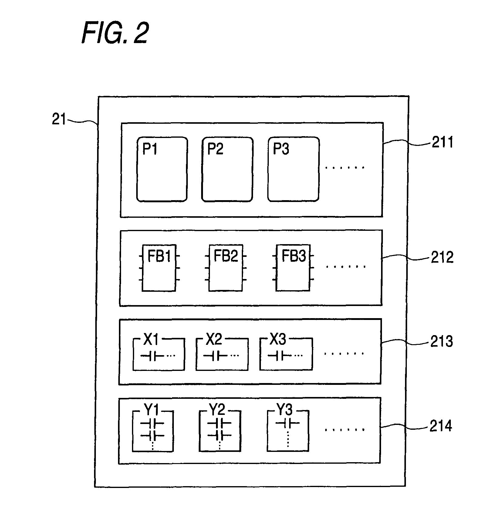
[0041]Next, a more detailed explanation will be given of this invention with reference to an embodiment thereof. In this embodiment, the explanation will be given of an application of the PLC according to this invention to the safety PLC. Referring to FIGS. 1 and 2, the construction of the safety PLC according to this embodiment will be explained. FIG. 1 is a schematic view of the safety PLC according to this embodiment. FIG. 2 is a schematic view of a system storage unit 21.

[0042]The safety PLC according to this embodiment includes, as shown in FIG. 1, I / O modules 11, 12; a CPU module 2; an input / output bus 3; and a personal computer (hereinafter referred to as a PC) 4. The connections of the input / output bus 3 to the I / O modules are referred to connecting points (300, 301, . . . ) in order from the side of the CPU module.

[0043]The I / O module 11 is electrically connected to the connecting point 300 of the input / output bus 3. The I / O module 11 is an S-STP module to which a light cur...


PUM


Abstract

The PLC according to this invention includes I / O modules, a CPU module, an input / output bus, and a PC having a display. The CPU module includes a control program storage unit which previously stores an intrinsic control program in which operation processing and an input / output information item are packaged; a library which previously stores the function block representing the operation processing; and a header file which previously stores equivalent input / output information equivalently representing the input / output information by a graphical language. Referring to the library and header file, PC causes the execution program created and stored in the main storage unit to be displayed on the display by the function block and equivalent input / output information item.

Description

[0001]This application is based upon and claims the benefit of priority of Japanese Patent Application No. 2007-172465 filed on Jun. 29, 2007, the contents of which are incorporated herein by reference in its entirety.BACKGROUND OF THE INVENTION[0002]This invention relates to a PLC (programmable logic controller).[0003]The PLC includes an I / O module to which an external device is electrically connected, a CPU module which executes an execution program for controlling the external devices through the I / O module, etc. The PLC permits a user to freely program the execution program. However, in order to program the execution program, considerable knowledge on the PLC is required. Namely, in order that the user creates the execution program, considerable knowledge and labor are required.[0004]Now, as an example of the PLC, a safety PLC is cited. In the safety PLC, advanced knowledge on safety control as well as the knowledge on the PLC is required. The safety PLC includes an I / O module t...

Claims


Application Information

Patent Timeline
Patent Type & Authority Patents(United States)
IPC IPC(8): G06F19/00G05B15/00G06F9/44G05B11/01
CPCG05B19/058G05B2219/13052G05B2219/14012G05B2219/13099G05B2219/13152G05B2219/13053
Inventor IKEGAMI, KENICHIARAKI, TSUTOMU
Owner JTEKT CORP
Why Eureka
Try Eureka