
Method and apparatus for automatic generation of information system user interfaces

a technology of information system and user interface, applied in the field of user interface and software engineering, can solve problems such as delay, bugs in business logic code itself, and inability to use prior art ui specification tools,

Inactive Publication Date: 2011-05-10
SOSY
View PDF36 Cites 158 Cited by
  • Summary
  • Abstract
  • Description
  • Claims
  • Application Information

AI Technical Summary

Problems solved by technology

The problems with prior art User Interface (UI) models and code generation tools are the following: UI specification methods do not consider enough the domain model (the functionality of the application).
Coding the business logic separately may lead to bugs in integration with the UI and bugs in the business logic code itself.
This lengthens the delay from conception to first sales in the market (time to market) because of possibly long delays in debugging the business logic code.
Furthermore, these prior art UI specification tools do not have: a precise, unambiguous semantics which can be validated to eliminate bugs in the UI code; translators that can generate UI code automatically from the validated specification of the user interface and able to connect with a generated business logic component; and a persistence layer also generated to conform an entirely automatic generated application.
On the other hand, methods and notations for the specification of functional requirements of computer programs (tools to define models of the business logic of a program) such as OMT or UML do not consider user interface requirements as well.
This produces synchronization problems whenever one of the specification changes.
In other words, when one of the specifications changes, the other specification “breaks” and code written implementing this other specification will no longer work with the code written implementing the first specification.
This requires expensive and time consuming reworking of the second specification.
Such code cannot be compiled directly and needs hand coding before a program which can run as a final application exists.
Previous UI modeling tools do not present a set of primitives that can be invoked to specify the elements of a user interface for business applications.
However, these prior art tools propose very low level primitives that can not be used in medium-sized industrial projects without suffering scalability problems.
Academic research about UI modeling tools such as iUML, Wisdom or CTT has resulted in tools which have not been tested in industrial projects and has not been fine-tuned for such scalability requirements.
As a result, this makes it impossible to generate validated specifications of the User Interface Model (Presentation Model) and bug-free code from an imprecise specification.

Method used


Image

  • Method and apparatus for automatic generation of information system user interfaces
  • Method and apparatus for automatic generation of information system user interfaces
  • Method and apparatus for automatic generation of information system user interfaces

Examples


Embodiment Construction

[0080]The system described herein provides a method and apparatus for producing fully functional user interface program code for computer programs being developed using the software production system and other information systems with modeling tools and time savings from concept to working code heretofore unknown.

[0081]The software production system has the following characteristics:

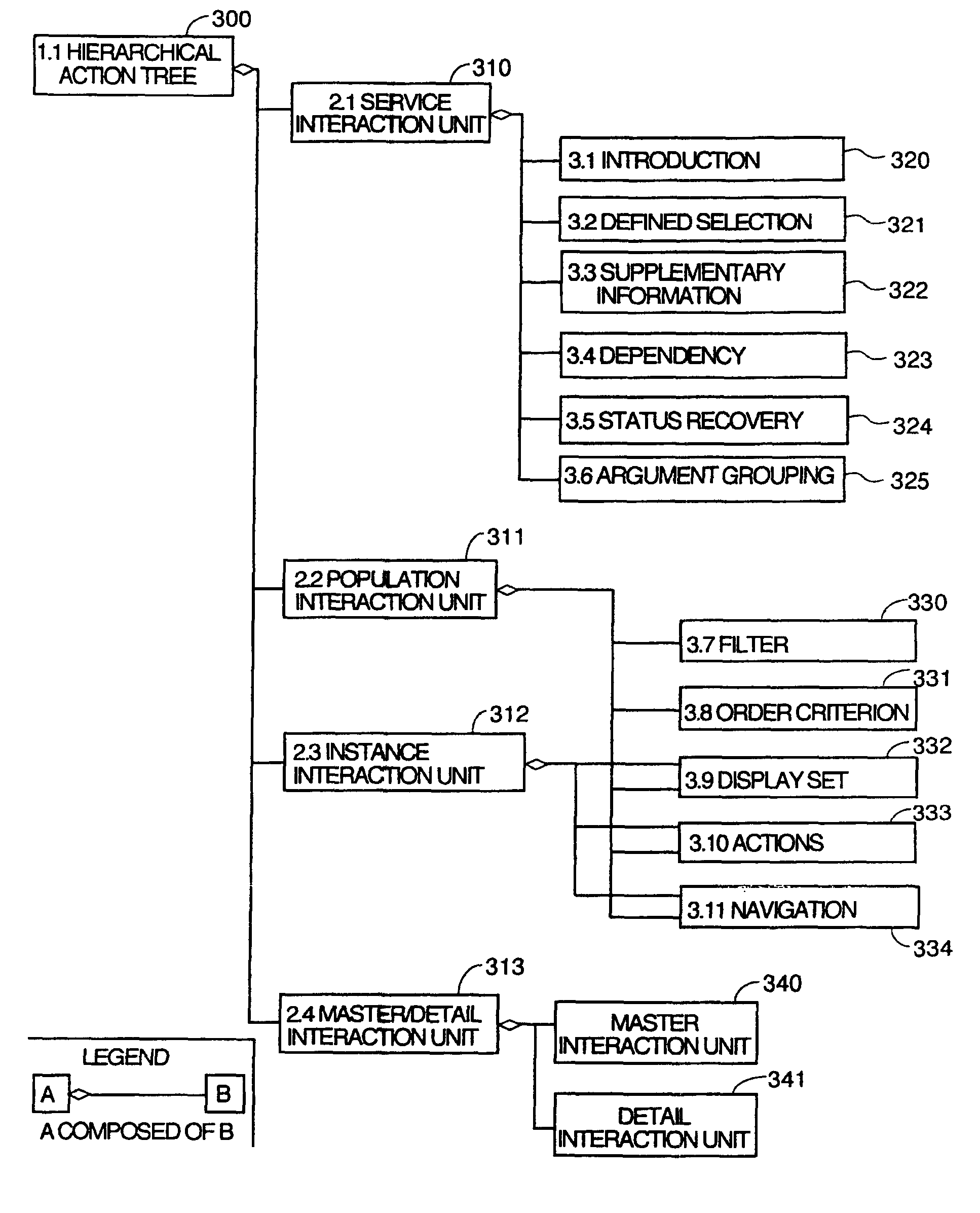
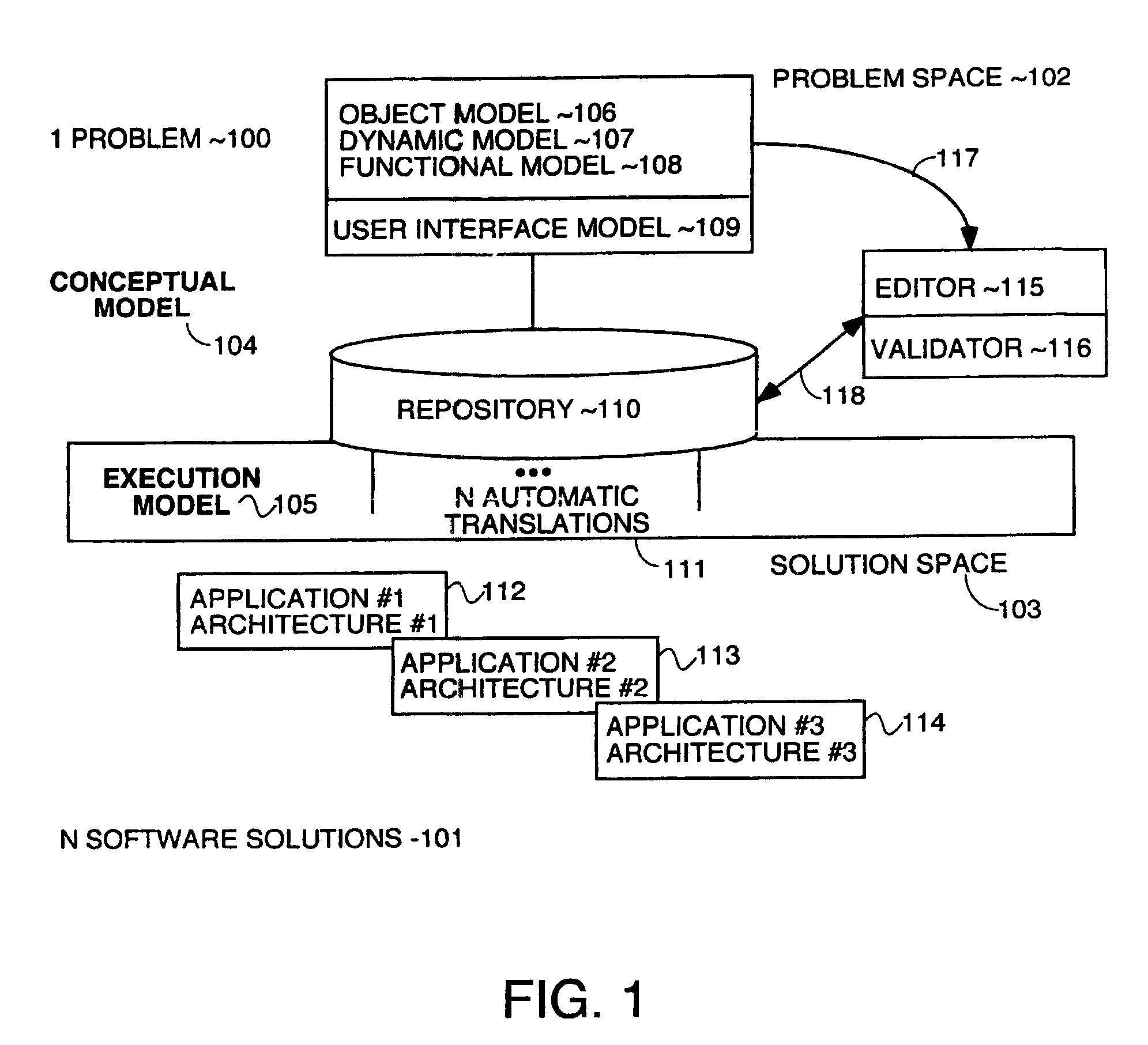
[0082](1) The software production system contains tools to define a unique specification model to facilitate modeling both functional aspects of the computer program being defined using the software production system and its user interface thereby enabling the production of a single model which fully specifies both the business logic and the user interface (as well as other things) thereby eliminating the synchronization problem between functional and user interfaces requirements that existed in the prior art.

(2) The software production system is supported by a meta-model having among other things, a set...


PUM


Abstract

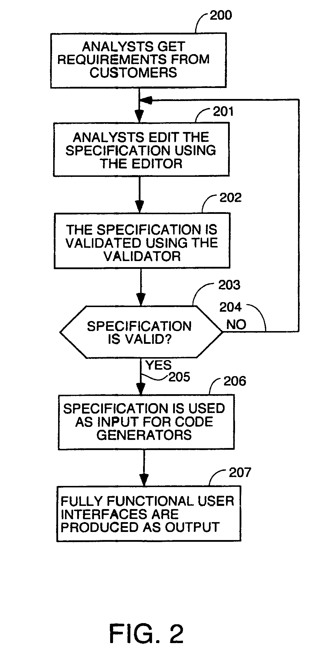
A system for automatic software production including specification and automatic generation of user interfaces is disclosed. A graphical editor presents diagrams and textual interactive dialogs which are used to enter requirements data defining the desired structure and behaviour of an application program being designed. The requirements data is automatically converted to formal counterparts in a formal language to create a Formal Specification. The Formal Specification is stored in translation structures which are object in memory taking the form of classes which have methods to use the requirements data to articulate source code templates which become source code components in the final output code. A Presentation Model based in a pattern language is used to specify a Presentation Model) using elements of the pattern language as meta-model building blocks which are articulated with requirements data that defines the specifics of the desired user interface.

Description

CROSS REFERENCE TO RELATED APPLICATIONS[0001]This is a divisional of prior U.S. patent application Ser. No. 10 / 356,250, filed Jan. 31, 2003, (now U.S. Pat. No. 7,334,216) which was a continuation-in-part of a prior U.S. patent application entitled Automatic Software Production System, Ser. No. 09 / 872,413, filed Jun. 1, 2001, (now U.S. Pat. No. 7,278,130) which was a continuation-in-part of prior U.S. patent application of the same title, Ser. No. 09 / 543,085, filed Apr. 4, 2000 (now U.S. Pat. No. 6,681,383) which are hereby incorporated by reference. Two other CIPS of Ser. No. 09 / 543,085, filed Apr. 4, 2000 exist having Ser. Nos. 09 / 872,087 (now abandoned) and 09 / 872,333, both filed Jun. 1, 2001 (now U.S. Pat. No. 7,137,100).REFERENCES[0002]Pedro J. Molina, Oscar Pastor, Sofia Marti, Juan J. Fons and, Emilio Insfran. “Specifying Conceptual Interface Patterns in an Object-Oriented Method with Code Generation” In Proceedings of 2nd IEEE Workshop on User Interfaces for Data Intensive Sy...

Claims


Application Information

Patent Timeline
Patent Type & Authority Patents(United States)
IPC IPC(8): G06F7/00G06F17/30G06F9/44G06F9/46G09G5/00
CPCG06F8/35G06F17/30371G06F8/38G06F16/2365
Inventor MOLINA-MORENO, PEDRO JUANPASTOR-LOPEZ, OSCARMOLINA-UDAETA, JUAN CARLOSBARBERA-ALONSO, JOSE MIGUEL
Owner SOSY
Learn More