
Dynamic preconditioning of a B+ tree

a database management system and dynamic preconditioning technology, applied in the field of database management system data structure, can solve the problems of different performance and scaling problems, and the inability of dbmss to handle sequential inserts concurrently,

Active Publication Date: 2011-05-10
UNISYS CORP
View PDF17 Cites 5 Cited by
  • Summary
  • Abstract
  • Description
  • Claims
  • Application Information

AI Technical Summary

Benefits of technology

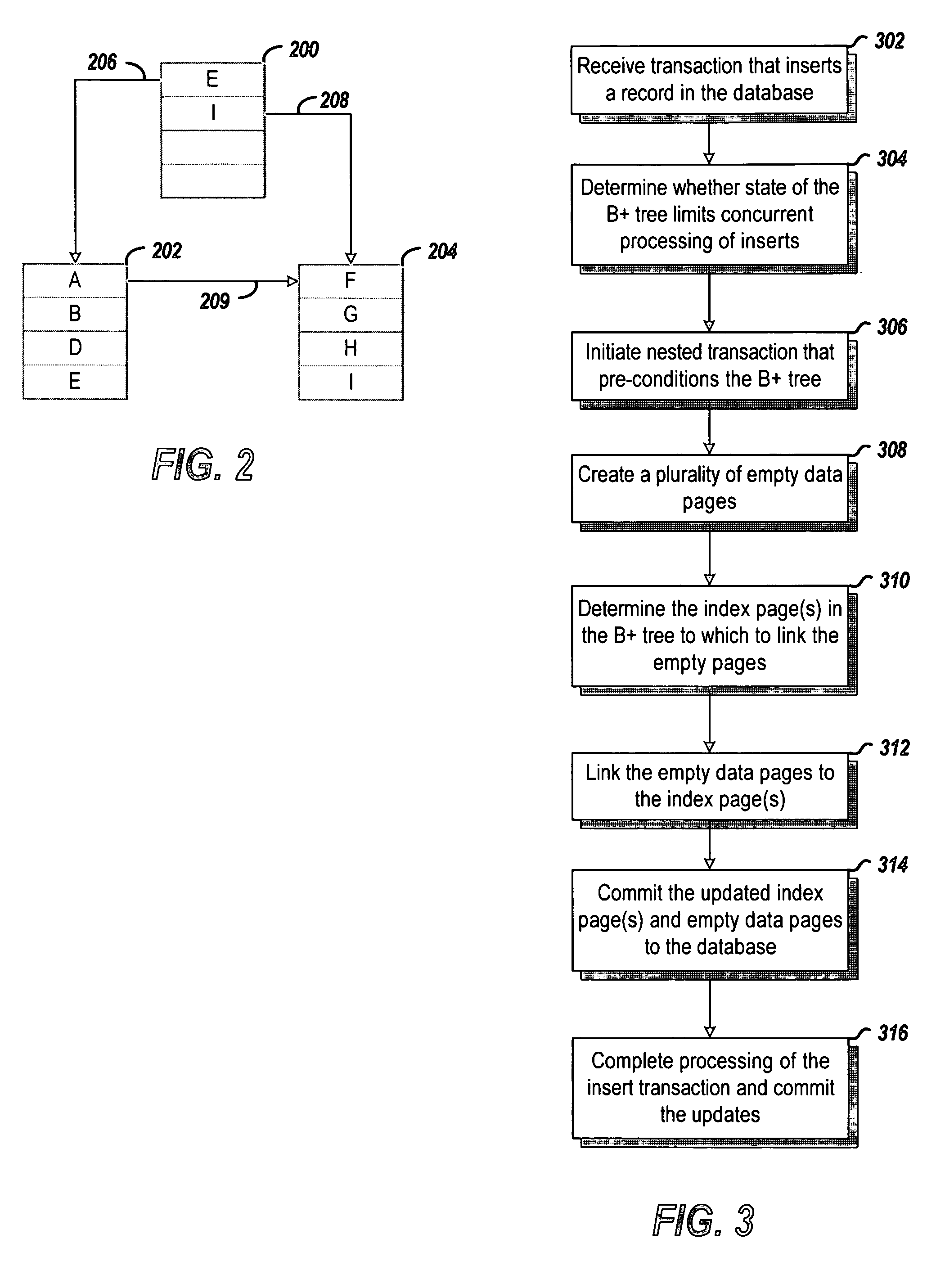
[0008]The various embodiments of the invention provide methods and systems for processing a B+ tree data structure for data records of a database. In one embodiment, a DBMS detects in a first transaction a first insert operation to a first data page of a first index page in the B+ tree data structure and then determines whether performing the first insert operation would block a second insert operation in a second transaction concurrent with the first transaction. At least one empty second data page is created in response to determining that the second insert operation would be blocked by the first insert operation. One or more index pages in the B+ tree data structure are updated to include the at least one second data page in the B+ tree data structure. The updated one or more index pages and at least one second data page are committed to retentive storage. Data specified in the first transaction is written to the first data page after committing the one or more index pages. The first data page is committed to retentive storage after writing the data to the first data page.

Problems solved by technology

Some DBMSs cannot handle concurrent inserts of sequential records because the records are logically inserted on the right-most page of the B+tree, and the selected database recovery approach uses page level recovery rather than record level recovery.
Where restrictions on concurrency may pose a problem, a user may insert dummy records and then delete the records to create the index and data pages for later use in sequentially inserting legitimate records.
However, inserting and deleting the required dummy records may be time consuming, error prone, and cause different performance and scaling problems.

Method used


Image

  • Dynamic preconditioning of a B+ tree
  • Dynamic preconditioning of a B+ tree
  • Dynamic preconditioning of a B+ tree

Examples


Embodiment Construction

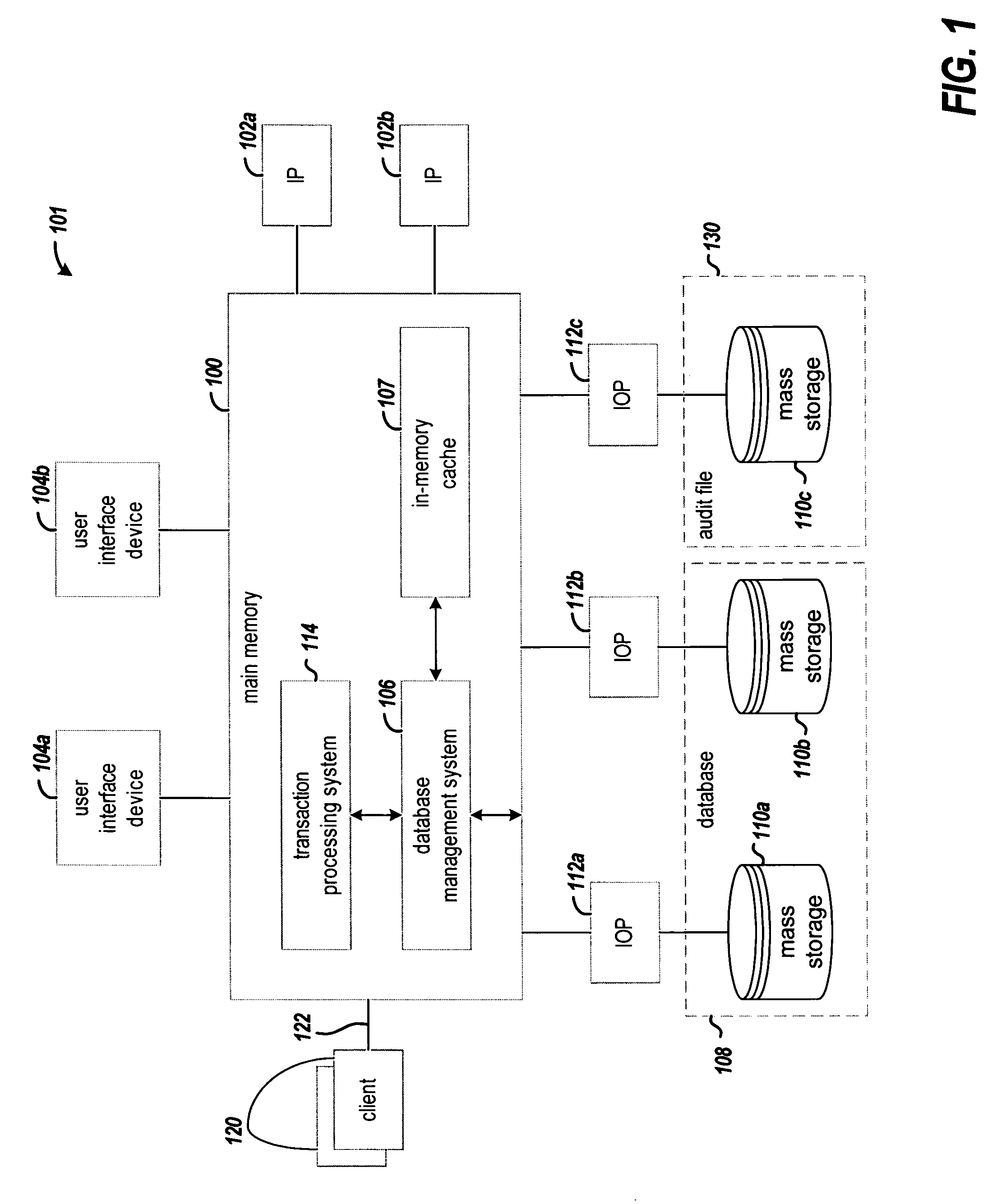
[0026]FIG. 1 is a block diagram of an example data processing system 101 in which various embodiments of the invention may be implemented. The example system illustrates a large-scale data processing system with multiple instruction processors (IPs) 102a and 102b. However, those skilled in the art will recognize that other types of data processing systems, such as a personal computer or a workstation may be used. The system includes a main memory 100 that is coupled to one or more IPs 102a and 102b. The memory may also be directly or indirectly coupled to one or more user interface devices 104a and 104b, which may include dumb terminals, personal computers, workstations, sound or touch activated devices, cursor control devices such as mice, printers, or any other known device used to provide data to, or receive data from, the data processing system.

[0027]A database management system (DBMS) 106 is resident main memory 100 and executes on IPs 102a and 102b to manage and provide access...


PUM


Abstract

Various approaches for processing a B+ tree data structure are described. In one approach, in a first transaction a first insert operation to a first data page of a first index page in the B+ tree data structure is detected, and then it is determined whether performing the first insert operation would block a second insert operation in a second transaction concurrent with the first transaction. At least one empty second data page is created in response to determining that the second insert operation would be blocked by the first insert operation. The B+ tree data structure is updated to include the at least one second data page in the B+ tree data structure, and the updated index pages and second data page are committed to retentive storage. Thereafter, the first insert can be completed.

Description

FIELD OF THE INVENTION[0001]The present invention generally relates to data structures for a database management system.BACKGROUND[0002]Relational databases generally require that every record be uniquely identified by one or a combination of columns. The one or more columns that uniquely identify records is declared to be the primary key (PK) of the table.[0003]A B+tree data structure is often used to manage database records. In an example implementation, nodes that are leaves of the B+tree are data pages of database records, and nodes that are parents of the leaves are index pages. The index pages contain primary key values for referencing records in the data pages. The leaves are sequentially linked to provide sequential access to database records.[0004]In some applications a database management system (DBMS) can generally insert records into the database tables with no concurrency problems. For example, for a pre-assigned key such as a social security number (SSN), the order in ...

Claims


Application Information

Patent Timeline
Patent Type & Authority Patents(United States)
IPC IPC(8): G06F7/00G06F17/30
CPCG06F17/30327G06F16/2246
Inventor RITCHIE, ROGER V.BRUSO, KELSEY L.PLASEK, JAMES M.
Owner UNISYS CORP
Learn More