Modular initiator with integrated optical diagnostic

Active Publication Date: 2011-05-17
NAT TECH & ENG SOLUTIONS OF SANDIA LLC
View PDF21 Cites 5 Cited by
  • Summary
  • Abstract
  • Description
  • Claims
  • Application Information

AI Technical Summary

Problems solved by technology

These hot spots induce deflagrat...

Method used


Image

  • Modular initiator with integrated optical diagnostic
  • Modular initiator with integrated optical diagnostic
  • Modular initiator with integrated optical diagnostic

Examples


Embodiment Construction

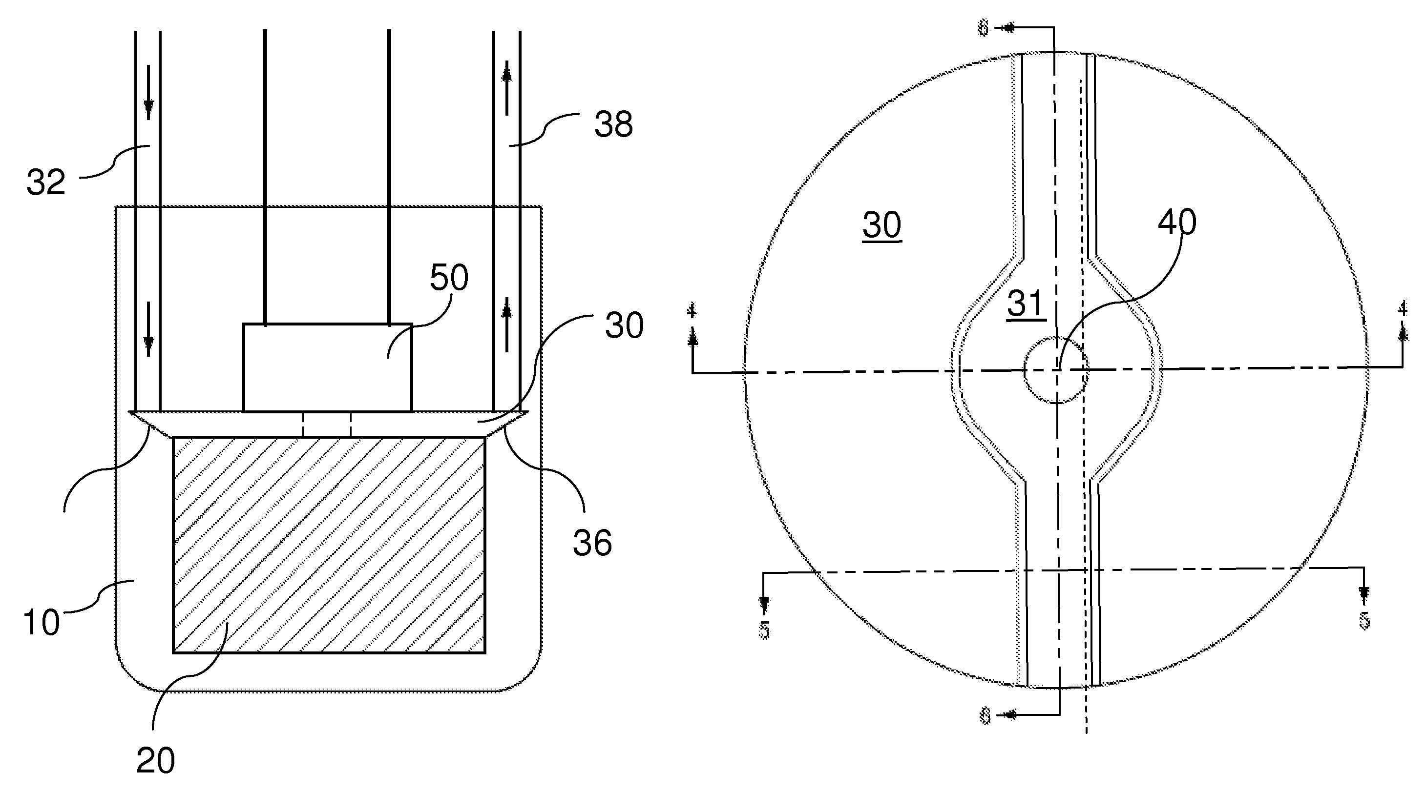
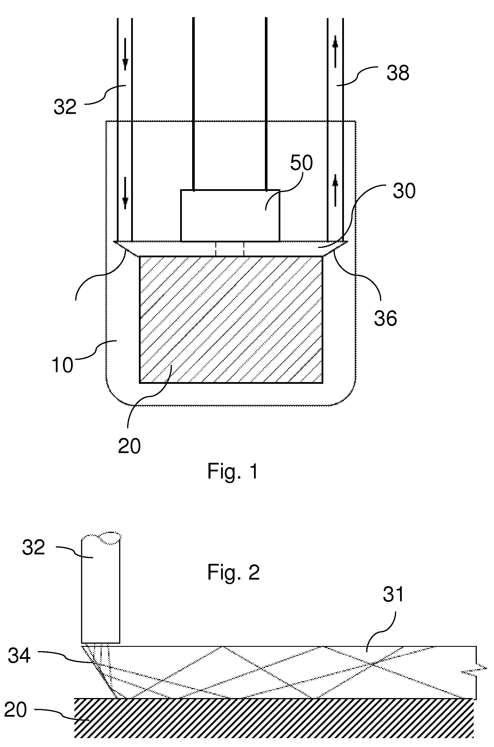
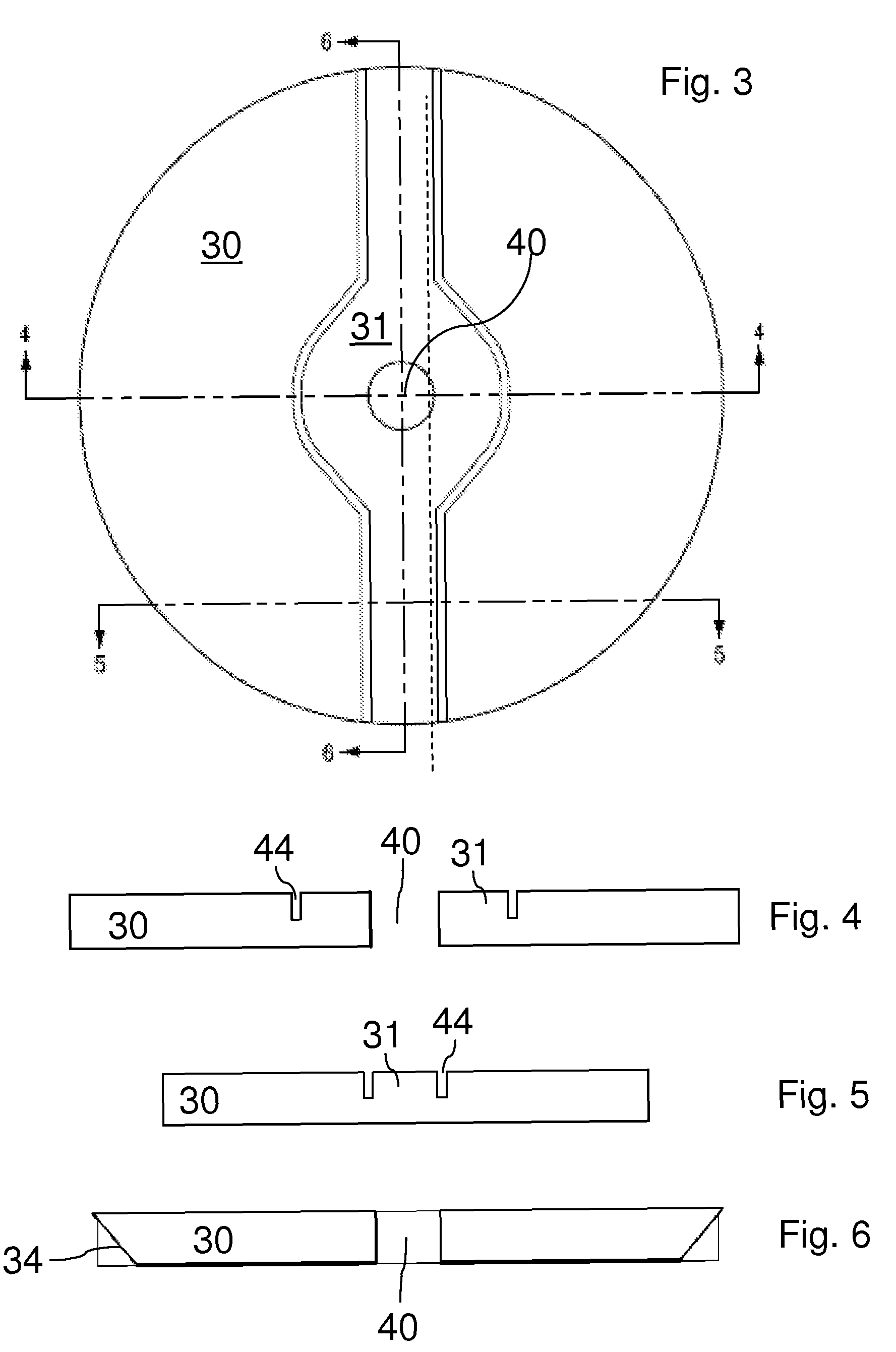
[0015]This invention comprises a slapper detonator which integrally incorporates a means for determining whether there has been degradation of the explosive and / or flyer plate in the explosive device that is to be initiated by the detonator. Embodiments of this invention take advantage of the barrel-like character of a typical slapper detonator design. The barrel assembly, being in direct contact with the energetic material as well as having access to the flyer plate material, may be designed to incorporate a diagnostic sensor to characterize the most critical elements of the detonator / initiator device. By incorporating an optical diagnostic device into the barrel assembly, one can monitor the state of the explosive material and / or the surface of the slapper. Such monitoring can be beneficial because the conditions of each play important roles in the proper functioning of a detonator / initiator device.

[0016]It is well established in the art that degradation of the explosive material ...


PUM


Abstract

A slapper detonator which integrally incorporates an optical wavequide structure for determining whether there has been degradation of the explosive in the explosive device that is to be initiated by the detonator. Embodiments of this invention take advantage of the barrel-like character of a typical slapper detonator design. The barrel assembly, being in direct contact with the energetic material, incorporates an optical diagnostic device into the barrel assembly whereby one can monitor the state of the explosive material. Such monitoring can be beneficial because the chemical degradation of the explosive plays an important in achieving proper functioning of a detonator/initiator device.

Description

[0001]This patent application claims priority benefit from U.S. provisional patent application Ser. No. 61 / 034,385, filed on Mar. 6, 2008, which is incorporated herein by reference.[0002]The United States Government has rights in this invention pursuant to Department of Energy Contract No. DE-AC04-94AL85000 with Sandia Corporation.BACKGROUND OF THE INVENTION[0003]This invention relates to devices for the initiation of chemical reactions. Initiators are devices that initiate a chemical reaction, and in many cases an initiator will initiate an energetic output which then can be used to drive another chemical reaction such as a pyrotechnic, propellant or detonation output. Initiators or detonators induce hot spots within the energetic material. These hot spots induce deflagration, ultimately leading to detonation. Hot spots can be induced in a number of ways, including heat, friction and compression.[0004]Applications which require precise timing typically use electrical initiators rat...

Claims


Application Information

Patent Timeline
IPC IPC(8): F42C13/02F42C15/00
CPCF42B3/18
Inventor ALAM, M. KATHLEENSCHMITT, RANDAL L.WELLE, ERIC J.MADDEN, SEAN P.
Owner NAT TECH & ENG SOLUTIONS OF SANDIA LLC
Why Eureka
Try Eureka