
Barrel assemblies used in blaster detonators

A technology for shocking detonators and barrels, which is applied to detonators and offensive equipment, can solve the problems of many parts, low processing efficiency, and difficult processing of barrels, so as to reduce processing difficulty, improve processing efficiency, and ensure normal operation. Effect

Active Publication Date: 2017-12-29
INST OF CHEM MATERIAL CHINA ACADEMY OF ENG PHYSICS
View PDF6 Cites 0 Cited by
  • Summary
  • Abstract
  • Description
  • Claims
  • Application Information

AI Technical Summary

Problems solved by technology

[0004] The purpose of the present invention is to provide a barrel assembly used in the shock-blade detonator, so as to solve the problems of many parts, difficult processing of the barrel and low processing efficiency in the current shock-blade detonator

Method used


Image

  • Barrel assemblies used in blaster detonators
  • Barrel assemblies used in blaster detonators
  • Barrel assemblies used in blaster detonators

Examples


Embodiment Construction

[0023] In order to make the purpose, technical solutions and advantages of the present invention clearer, the specific implementation manners of the present invention will be clearly and completely described below in conjunction with the accompanying drawings. Apparently, the described embodiments are part of the embodiments of the present invention, rather than All examples are not limitations of the present invention. Based on the embodiments of the present invention, all other embodiments obtained by persons of ordinary skill in the art without making creative efforts belong to the protection scope of the present invention.

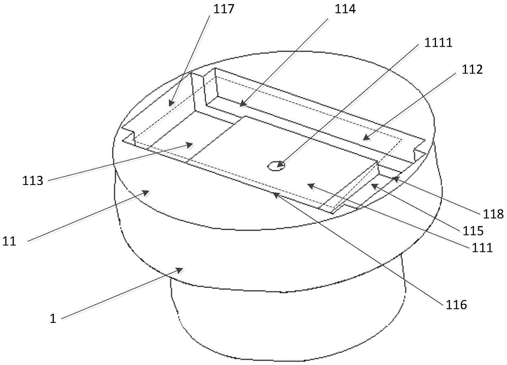
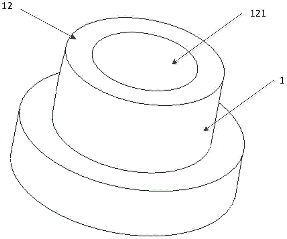
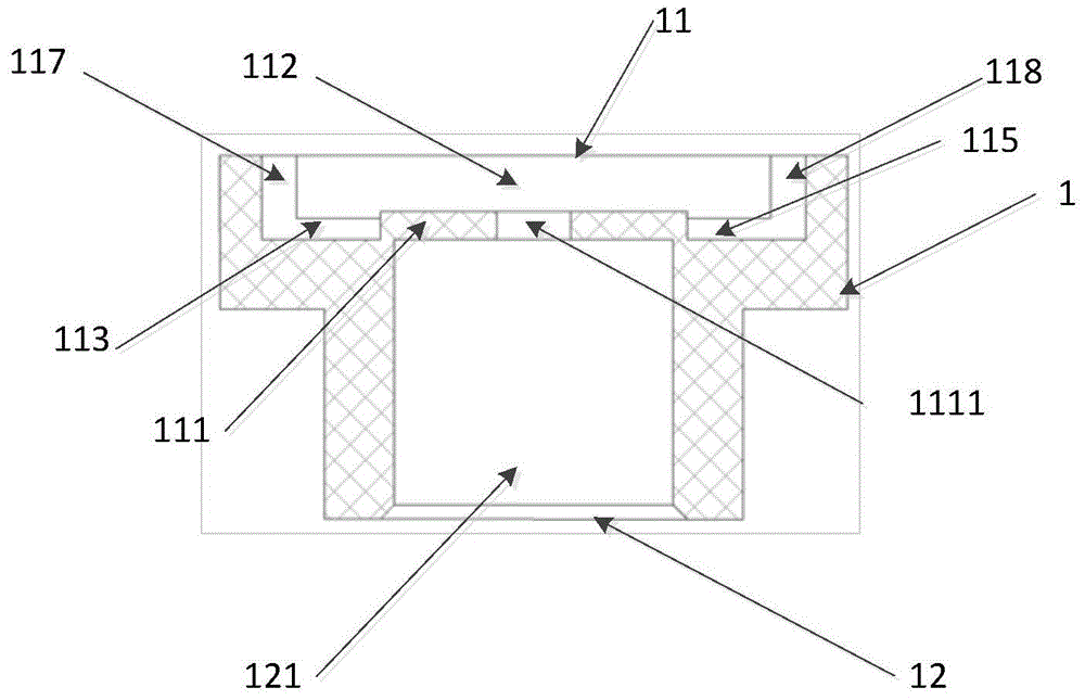
[0024] figure 1 A schematic structural view of the barrel assembly used in the shock-disk detonator provided by the embodiment of the present invention, figure 2 A structural schematic diagram of a barrel assembly used in a shock-disk detonator provided for an embodiment of the present invention, image 3 A cross-sectional view of a barrel assembly ...


PUM


Abstract

The present invention relates to the field of design of shock-blade detonators, and provides a barrel assembly used in shock-blade detonators to solve the problems of many parts, difficult barrel processing and low processing efficiency in current shock-blade detonators. The upper surface of the barrel assembly is provided with an explosion foil positioning hole, and the middle part of the explosion foil positioning hole is provided with a boss. The first electrode relief groove is provided at the extension of the first welding ribbon relief groove, and the second electrode relief groove is provided at the extension of the second welding ribbon relief groove . The technical scheme proposed by the invention integrates parts such as explosive foil positioning holes, electrode relief holes, welding ribbon relief holes, charge rings, barrels and other components, which reduces the processing difficulty of the barrel assembly and improves the efficiency of the barrel assembly. processing efficiency.

Description

technical field [0001] The invention relates to the design field of the shock-blade detonator, in particular to a barrel assembly used in the shock-blade detonator. Background technique [0002] Shock plate detonators are mainly composed of substrates, metal explosive foils, flyers, barrels, explosives, positioning seats, charge rings, shells, etc. Shock plate detonators have high requirements for safety and reliability. In the shock detonator, the barrel is located between the flyer and the explosive, and the function of the barrel is to cut the compressed flyer along the edge of the inner hole of the barrel into a round flyer equal to the diameter of the inner hole of the barrel, and in the hole Accelerate forward. At present, the size of the inner hole of the barrel commonly used at home and abroad is small, and the parameters such as thickness, aperture and eccentricity are relatively high, so the processing is difficult. Contents of the invention [0003] 【Technical...

Claims


Application Information

Patent Timeline
Patent Type & Authority Patents(China)
IPC IPC(8): C06C7/00
Inventor 王丽玲王亮
Owner INST OF CHEM MATERIAL CHINA ACADEMY OF ENG PHYSICS
Learn More