Injection drive apparatus for injection molding machine

a technology of injection molding machine and drive apparatus, which is applied in the direction of auxillary shaping apparatus, manufacturing tools, food shaping, etc., can solve the problems of large energy consumption of driving, and achieve the effect of reducing the load of the motor and increasing the yield rate of injection molding products

Active Publication Date: 2011-05-17
HWA CHIN MACHINERY +1
View PDF8 Cites 0 Cited by
  • Summary
  • Abstract
  • Description
  • Claims
  • Application Information

AI Technical Summary

Benefits of technology

[0008]Therefore it is a primary object of the present invention to provide an injection drive apparatus for injection molding machines in which a liquid plastic material is fed into a mold smoothly firstly and then the squeezing and injection of the plastic material are performed so as to reduce the load of a motor and increase the yield rate of the products.
[0013]Thereby the liquid plastic material is fed into the mold smoothly by the material feeding screw of the material feeding mechanism. Then a reaction force is created to push the material feeding screw when the material feeding hole is almost fully filled with the liquid plastic material. Now the slide mechanism assembled with the material feeding screw is also forced to move backward for buffering the reaction force. Next the injection mechanism is driven to move the drive screw so as to drive the slide mechanism pushing the material feeding screw to move forward and squeeze the plastic material for injection molding. Therefore, the load of the motor is reduced due to the two-stage action—feeding of the liquid plastic material into the mold smoothly at first and then the squeezing of the plastic material for injection. Moreover, the yield rate of the products produced by injection molding is increased.

Problems solved by technology

Moreover, due to heavier weight, the energy consumption for driving is large.

Method used


Image

  • Injection drive apparatus for injection molding machine
  • Injection drive apparatus for injection molding machine
  • Injection drive apparatus for injection molding machine

Examples


Embodiment Construction

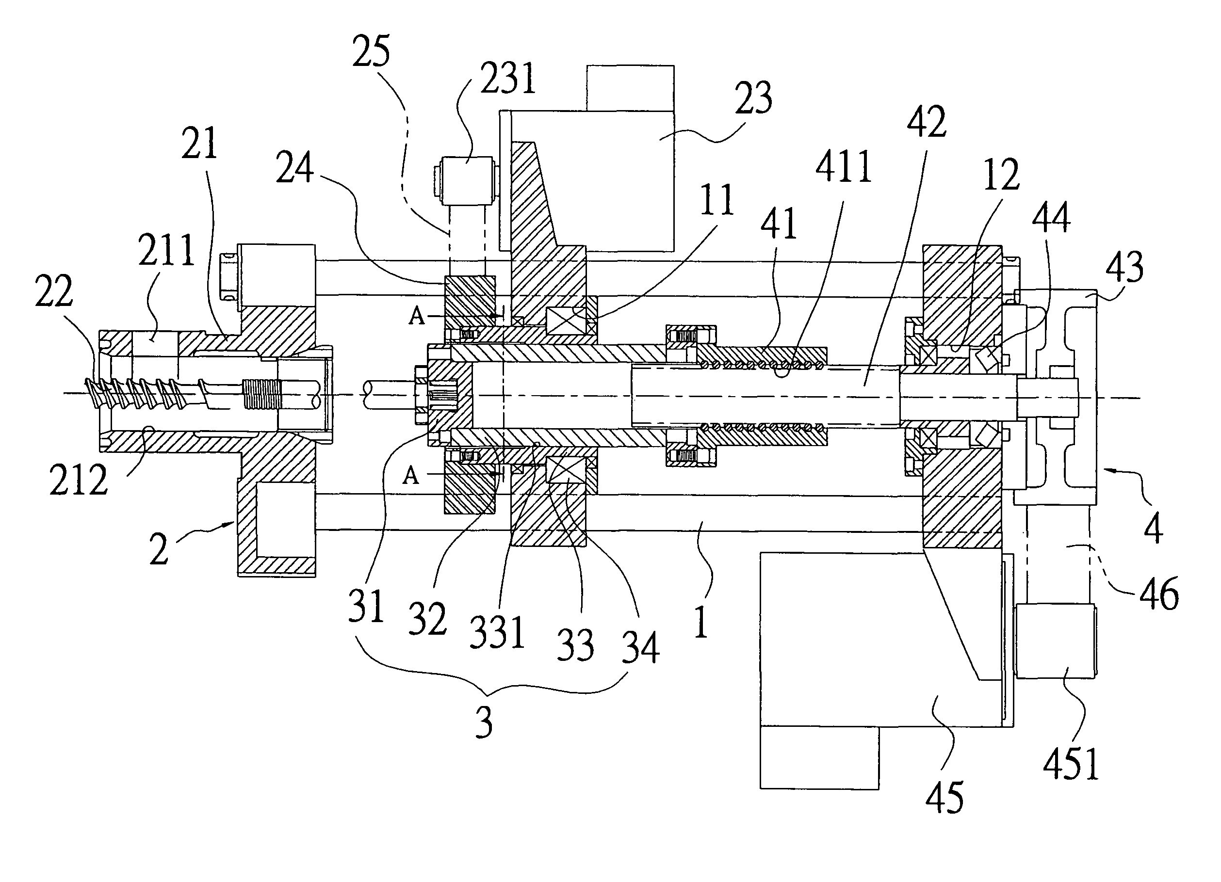
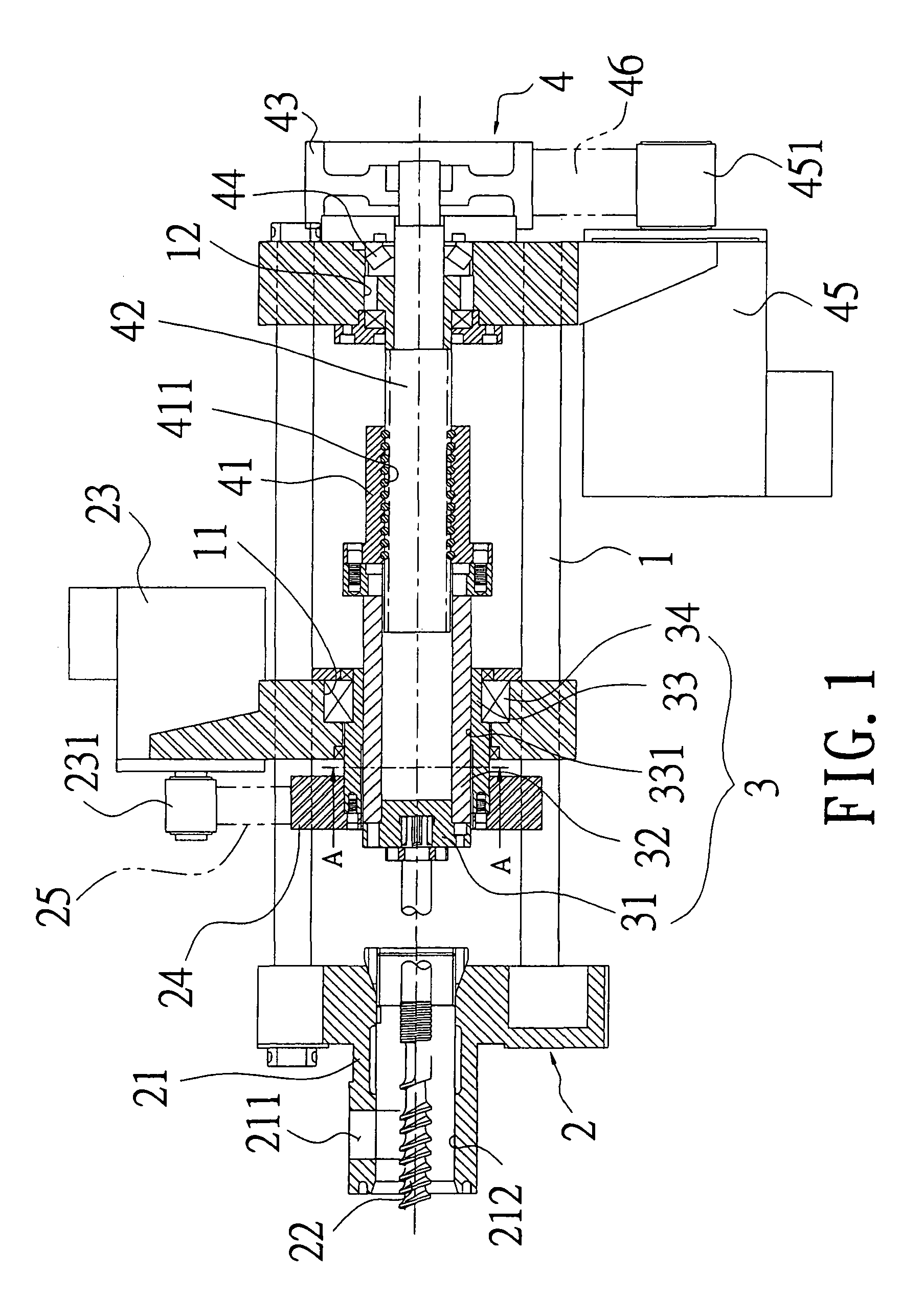
[0024]Refer to FIG. 1, an injection drive apparatus for an injection molding machine according to the present invention includes a machine platform 1 and a material feeding mechanism 2, a slide mechanism 3 and an injection mechanism 4 all arranged at the machine platform 1.

[0025]The material feeding mechanism 2 consists of a material feeder 21 connected and fixed with the machine platform 1, a material inlet 211 disposed over the material feeder 21 and a material feeding hole 212 arranged at a center of the material feeder 21. The material feeding hole 212 is connected with the material inlet 211 and a material feeding screw 22 is inserted through the material feeding hole 212. Moreover, the machine platform 1 is disposed with a material-feeding motor 23 and a conveyor belt 25 is arranged between a drive shaft 231 of the material-feeding motor 23 and a disc 24.

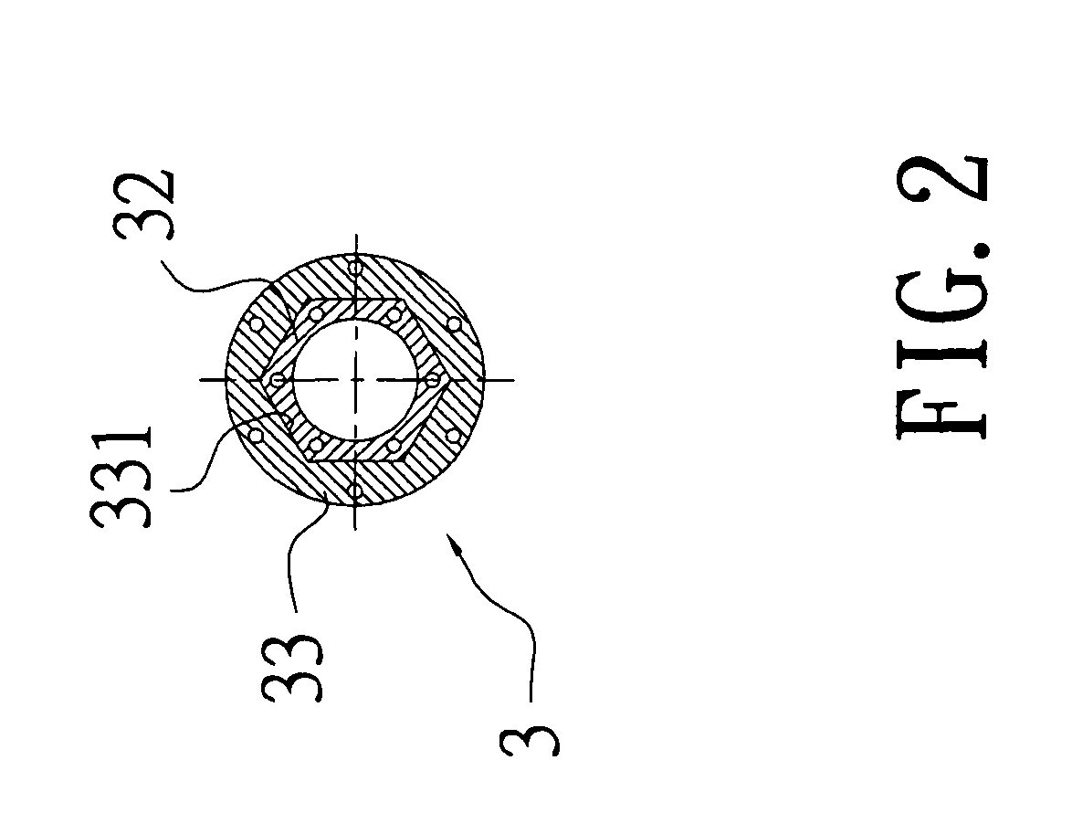
[0026]Also referring to FIG. 2, the slide mechanism 3 includes a sliding slave member 31 connected and assembled with a rear...


PUM

PropertyMeasurementUnit
shapeaaaaaaaaaa
yield rateaaaaaaaaaa
weightaaaaaaaaaa

Abstract

An injection drive apparatus for injection molding machines is revealed. Liquid material is fed into a mold smoothly by a material feeding screw of a material feeding mechanism. Then a reaction force is generated to push the material feeding screw when the material feeding hole is nearly full of the material. Thus the material feeding screw and the slide mechanism assembled therewith are pushed to move backward. Later the injection mechanism is driven by the slide mechanism to move and act on the drive screw. Thus the slide mechanism threaded with the drive screw is driven to push the material feeding screw moving forward and squeezing the material for injection molding. Therefore, the load of the motor is reduced dramatically and the yield rate of the products produced by injection molding is increased due to the two-stage action-feeding of the material and squeezing of the material for injection.

Description

BACKGROUND OF THE INVENTION[0001]1. Fields of the Invention[0002]The present invention relates to an injection drive apparatus for injection molding machines, especially to a driving mechanism for injection molding machines that reduces load of a motor and increases the yield rate of the injection molding products by two-stage action—initially feeding liquid plastic material into a mold smoothly and then squeezing the material for injection molding.[0003]2. Descriptions of Related Art[0004]As to servo injection molding machines available now, as shown in U.S. Pat. No. 5,129,808, a motor is used to drive two ball screws for further driving a rear end face, a metering motor, and related parts. The driving member includes a plurality of linear guides and guide bars that are difficult to maintain parallel to one another, move synchronously and control the precision. Moreover, due to heavier weight, the energy consumption for driving is large.[0005]Moreover, refer to U.S. Pat. No. 4,693,...

Claims


Application Information

Patent Timeline
Patent Type & Authority Patents(United States)
IPC IPC(8): B29C45/77
CPCB29C45/5008B29C2045/5028B29C2045/5024
Inventor WANG, JUI-HSIANG
Owner HWA CHIN MACHINERY
Why Eureka
Try Eureka