
Hierarchical virtual trunking over packet networks

a packet network and hierarchy technology, applied in the field of telecoms, can solve the problems of affecting the quality of streaming media required to carry voice communications, packet networks are prone to packet loss and delay, and telephony services, and achieve the effect of efficient and easy managemen

Inactive Publication Date: 2011-05-17
RPX CLEARINGHOUSE
View PDF46 Cites 23 Cited by
  • Summary
  • Abstract
  • Description
  • Claims
  • Application Information

AI Technical Summary

Benefits of technology

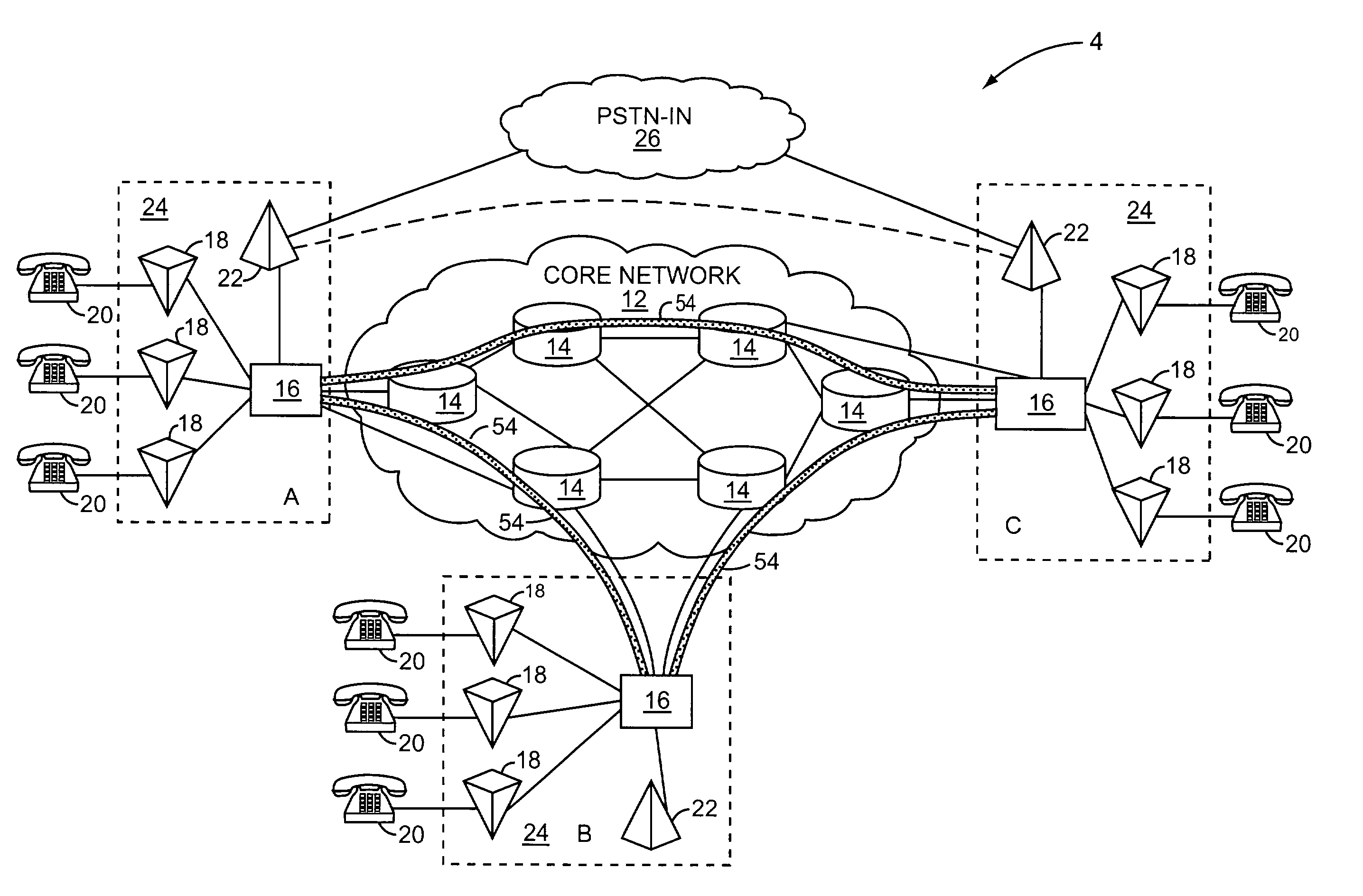
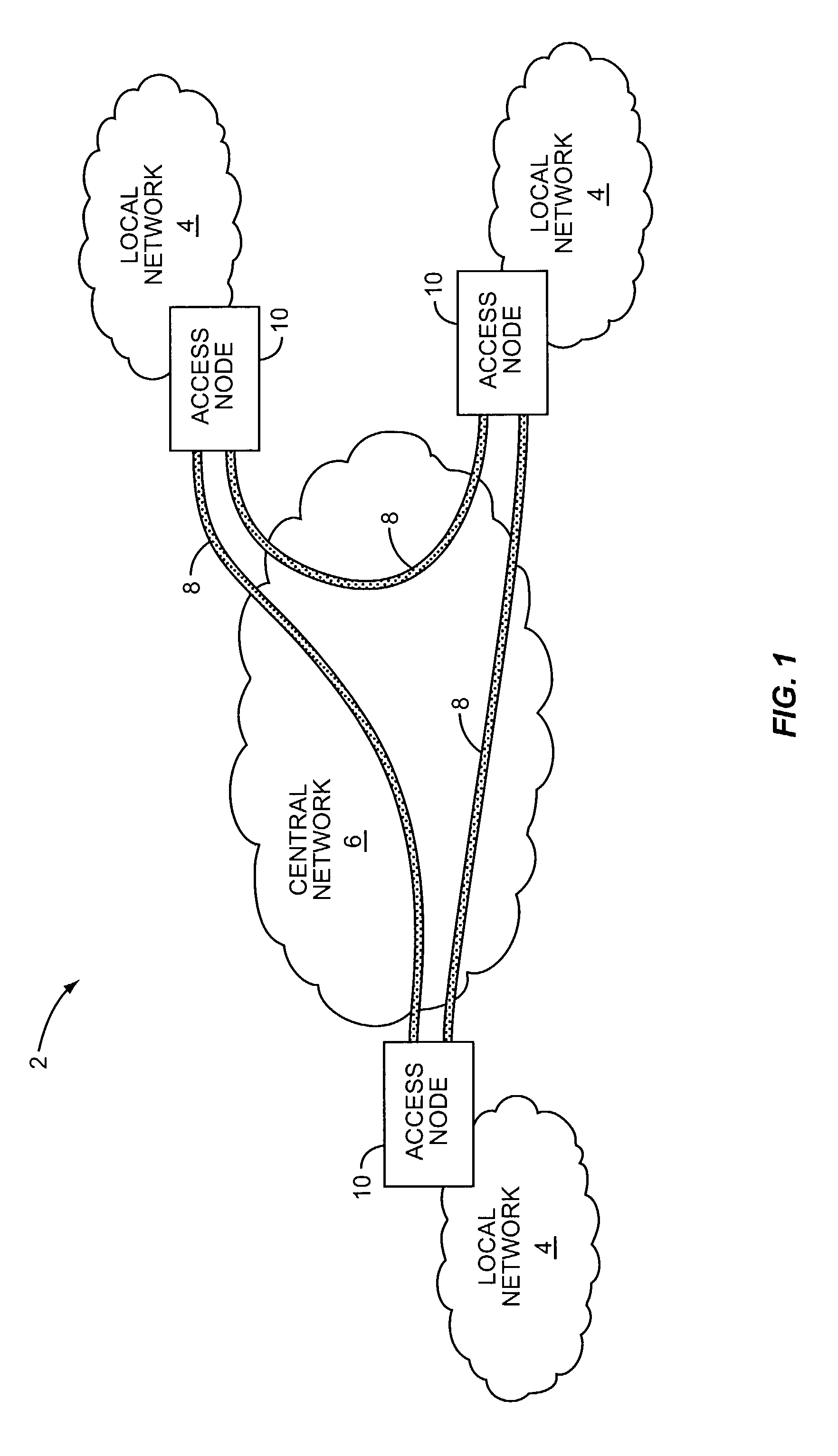
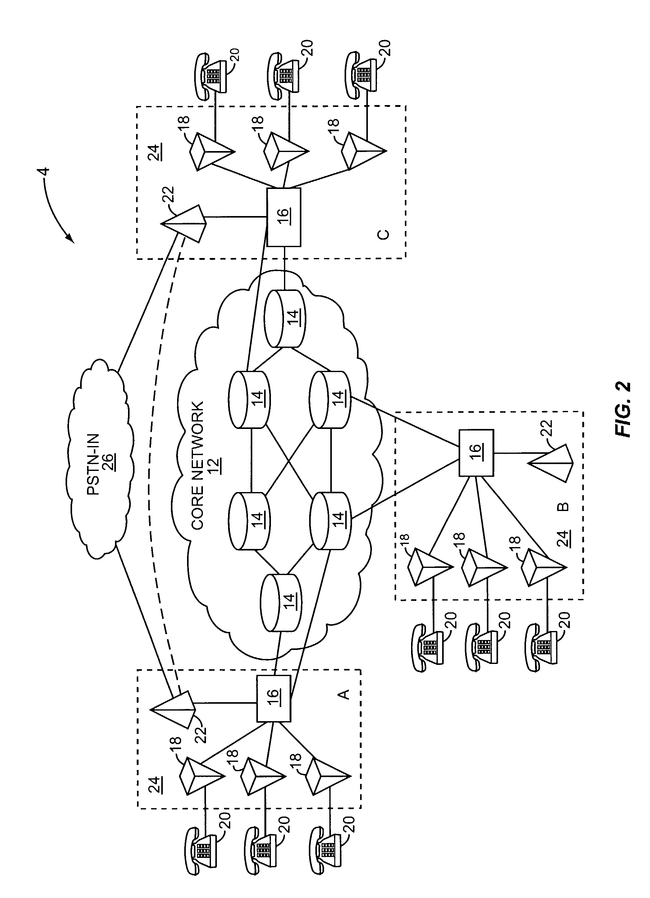
[0010]The invention provides for a hierarchical network infrastructure wherein a network of reserved paths may be established at each network level, and access between network levels is provided by an access node that terminates reserved paths on the connection networks. As such, the infrastructure is infinitely scalable and may support two or more network layers in an efficient and easy to manage manner.

Problems solved by technology

At the moment, there are several obstacles to providing telephony services on a packet network with the same level of performance and availability as is available on the PSTN today.
On the other hand, packet networks have been prone to packet loss and delays, which affect the quality of streaming media required to carry voice communications.
The bursty nature of packet communications makes controlling communication quality and ensuring sufficient bandwidth very difficult.
Traditional “fat pipe” models, which rely on the overall network to find a way to transmit the packets with the required quality of service levels, have not been completely successful.
Further, the integration of call processing for the PSTN and packet networks has proven difficult to manage.

Method used


Image

  • Hierarchical virtual trunking over packet networks
  • Hierarchical virtual trunking over packet networks
  • Hierarchical virtual trunking over packet networks

Examples


Embodiment Construction

[0027]The embodiments set forth below represent the necessary information to enable those skilled in the art to practice the invention and illustrate the best mode of practicing the invention. Upon reading the following description in light of the accompanying drawing figures, those skilled in the art will understand the concepts of the invention and will recognize applications of these concepts not particularly addressed herein. It should be understood that these concepts and applications fall within the scope of the disclosure and the accompanying claims.

[0028]The present invention establishes reserved paths between nodes in a packet network. Each reserved path has a defined bandwidth. Associated with each reserved path is a virtual trunk group. The virtual trunk group has the same bandwidth as the reserved path and supports a set number of channels. Telephony calls requiring media flows associated with a channel in the virtual trunk group will transport packets along the reserved...


PUM


Abstract

The present invention establishes reserved paths between nodes in a central packet network and in local networks attached to the central network. Each reserved path has a defined bandwidth and may be implemented as an LSP in an MPLS network or as a PVC in an ATM network. Associated with each reserved path is a virtual trunk group representing the same bandwidth as the virtual path. Telephony calls requiring media flows associated with a channel in the virtual trunk group will transport packets along the reserved path associated with the virtual trunk group. Access to the reserved path is limited to telephony media flows associated with a virtual trunk group to ensure adequate bandwidth at all times for the number of channels associated with the virtual trunk group. Backup reserved paths may be associated with the primary reserved path to provide the necessary redundancy required for voice-based telephony applications.

Description

[0001]This application claims the benefit of provisional patent application Ser. No. 60 / 367,676, filed Mar. 26, 2002, the disclosure of which is hereby incorporated by reference in its entirety.CROSS-REFERENCE TO RELATED APPLICATIONS[0002]The present application is related to U.S. application Ser. No. 10 / 175,122 filed Jun. 19, 2002, currently pending, the disclosure of which is incorporated herein by reference, in its entirety.FIELD OF THE INVENTION[0003]The present invention relates to telecommunications, and in particular to ensuring quality of service levels over packet networks.BACKGROUND OF THE INVENTION[0004]There is a growing interest in the convergence of the public switched telephone network (PSTN), the Internet and other internets and intranets. The convergence of these networks requires technology that facilitates interworking in a uniform and effective manner. The next generation of unified networks will provide an open and scalable architecture to accommodate multiple v...

Claims


Application Information

Patent Timeline
Patent Type & Authority Patents(United States)
IPC IPC(8): H04L12/28H04L12/56H04L12/26H04L12/66G06F15/173
CPCH04L12/5692H04L12/5695H04L45/00H04L45/245H04L47/724H04M7/0057H04M7/1275H04L45/50Y02B60/33H04L47/70Y02D30/50
Inventor SYLVAIN, DANY
Owner RPX CLEARINGHOUSE
Learn More