Method and system of monitoring a data transmission link, particularly an optical, bidirectional data transmission link

a data transmission link and optical technology, applied in the field of optical data transmission link monitoring, can solve the problems of increasing hardware and software costs, increasing operating costs, and achieving the effect of simple and economical

Inactive Publication Date: 2011-05-17
ADVA OPTICAL NETWORKING SE
View PDF6 Cites 7 Cited by
  • Summary
  • Abstract
  • Description
  • Claims
  • Application Information

AI Technical Summary

Benefits of technology

[0006]The present invention is devised to provide a method for monitoring a data transmission link, especially an optical, bidirectional data transmission link, with which in a simple and economical way performance data of the overall data transmission via the transmission link or individual services can be determined. In addition, the invention presents devices for implementing such methods.

Problems solved by technology

In addition, in this way a detailed error analysis is possible in the case of a fault.
However, the use of active transmission technology for determining performance data at a demarcation line, especially for the purpose of monitoring special services, leads to an increase in the hardware and software costs, as well as to an increase of the operating costs due to the necessary maintenance and commissioning of the active transmission technology at the customer site.
In addition, network availability decreases due to the ever-present failure probability of active transmission technology.

Method used


Image

  • Method and system of monitoring a data transmission link, particularly an optical, bidirectional data transmission link
  • Method and system of monitoring a data transmission link, particularly an optical, bidirectional data transmission link
  • Method and system of monitoring a data transmission link, particularly an optical, bidirectional data transmission link

Examples


Embodiment Construction

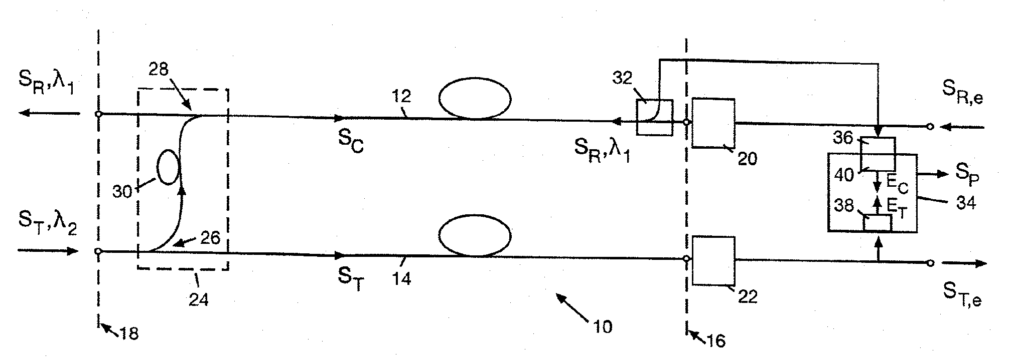
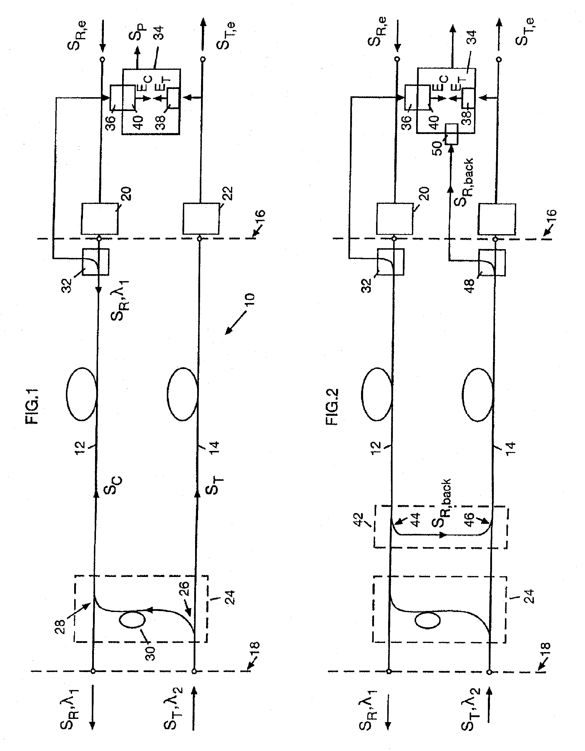
[0025]The optical transmission link 10 shown in FIG. 1 includes two optical waveguides 12, 14, of which the optical waveguide 12 transmits an optical receive signal SR at the wavelength λ1 from a remote end 16 to a local end 18 and an optical waveguide 14 transmits an optical transmit signal ST at the wavelength λ2 from the local end 18 to the remote end 16. At the remote end 16 of the transmission link 10 there is an electro-optical converter unit 20, which performs an electro-optical conversion of the electrical receive signal SR,e into the optical receive signal SR and an opto-electrical converter unit 22, which converts the remote-side, received optical transmit signal ST into an electrical transmit signal ST,e. In practice, the electro-optical converter unit 20 and the opto-electrical converter unit 22 can be contained, for example, in one channel card.

[0026]At the local end 18 of the transmission link 10 there is a splitting-and-delay unit 24, which includes a first coupler 26...


PUM


Abstract

Systems and methods for monitoring a data transmission link, especially an optical, bidirectional data transmission link, in which a digital transmit signal is transmitted on a first transmission path from a local end of the data transmission link toward a remote end of the data transmission link. A portion of the power of the transmit signal sent at the local end is transmitted, delayed by a non-zero delay time on a second transmission path as a control signal toward the remote end of the data transmission link. Both signals are received at the remote end and are tested for the presence of events of a predetermined type. A conclusion can be reached on the quality of the transmission link as a function of a time correlation and frequency of the appearance of events in the received transmit signal and in the received control signal.

Description

CROSS REFERENCE TO RELATED APPLICATIONS[0001]Pursuant to 35 U.S.C. §119, this application claims the benefit of prior German Patent Application No. 10 2007 015 628.8, filed Mar. 29, 2007. The prior application is hereby incorporated by reference in its entirety for all purposes.TECHNICAL FIELD[0002]The invention relates to a method for monitoring a data transmission link, especially an optical data transmission link, with the goal of reaching a conclusion on the performance of the overall data transmission or on an individual service as part of the overall data transmission to a certain endpoint of the transmission link, a so-called demarcation line.BACKGROUND[0003]For the commercial preparation of Ethernet-based connection services, so-called Service Level Agreements are usually a central component of the contract between the network operator or service provider and the customer. Such Service Level Agreements describe in detail a minimum continuous performance of data transmission ...

Claims


Application Information

Patent Timeline
Patent Type & Authority Patents(United States)
IPC IPC(8): H04B10/08H04B10/079
CPCH04B10/0795
Inventor HINDERTHUR, HENNING
Owner ADVA OPTICAL NETWORKING SE
Why Eureka
Try Eureka