Expandable slide and lock stent

a technology of stents and slides, applied in the field of expandable medical implants, can solve the problems of mechanical and vasodynamic limitations of stents, limitations related to deployment, limitations related to vasodynamic capabilities, etc., and achieve the effect of increasing the potential for slipping and denting

Inactive Publication Date: 2011-05-24
REVA MEDICAL
View PDF439 Cites 103 Cited by
  • Summary
  • Abstract
  • Description
  • Claims
  • Application Information

AI Technical Summary

Benefits of technology

[0010]In accordance with at least one of the embodiments disclosed herein is the realization that a vascular implant may experience a number of mechanical limitations related to delivery. For example, some portions of the vasculature are curved or substantially non-cylindrical. These portions of the vasculature have proven difficult to deploy stent devices. Sometimes, the curvature of the vessel can cause a deployed stent to fold, especially in stents with insufficient flexibility in the design. Curved vessels further increase the potential for hinging and denting as described in further detail below.

Problems solved by technology

Although promising candidates for use as implantable devices and device components, these known radially expandable and slidably engaged stents have mechanical and vasodynamic limitations of which the inventors of the present application set out to address.
These limitations can be characterized as deployment related limitations, and limitations related to vasodynamic capabilities.
Intravascular space; especially that of a patient in need of a vascular implant, is generally inconsistent and varies upon the individual with respect to curvature, plaque buildup and other luminary obstructions.
However, even after such procedures, vascular characteristics remain patient delineated and largely inconsistent.
These portions of the vasculature have proven difficult to deploy stent devices.
Sometimes, the curvature of the vessel can cause a deployed stent to fold, especially in stents with insufficient flexibility in the design.
The inventors of the present application have recognized a problem with known radially expandable and slidably engaged stents, the problem herein referred to as “hinging.” Many slidably-engaged expandable stents possess a common limitation where the engagements are generally longitudinally aligned, thereby inherently creating an alignment of failure points.
A failure point is a weakness in a stent design, usually a point where two parts are joined together in a less than permanent fashion such as an engagement between slidably-engaged radial modules.
When an amount of radial pressure is exerted on the expanded stent, the stent tends to buckle or fold at the failure point.
A series of failure points that are longitudinally aligned can act as a perforation in the material and cause a substantial weakness and propensity for hinging.
Another plaque-related problem is herein referred to as “denting.” Denting is caused by an inherent device pattern weakness where a vaso-occlusion can drive a portion of at least one stent module into the luminary space, thereby substantially enhancing the effect of the vaso-occlusion.
Such an occlusion or dent can lead to collection of thrombus or flow distortions which are problematic and can increase stenosis.
Vascular plaque is typically non-uniform and often forms in a bulky occlusion, such an occlusion can place added stress on the stent via a point force, and increase the risk of hinging or denting.
The inventors of the present application have recognized that denting can significantly dampen or interfere with vasodynamics, and therefore may cause an increase in realized stenosis.
Furthermore, denting may not be immediately apparent to the implanting physician where a polymer stent is adapted for increased ductility over time.
Furthermore, the inventors of the present application recognized detriments such as a propensity for denting where the design pattern provides unsupported adjacent components.
The likelihood of denting occurrences is increased for stent patterns lacking the support of a structural backbone, especially when there are unsecured corners or other points having a propensity for weakness.

Method used


Image

  • Expandable slide and lock stent
  • Expandable slide and lock stent
  • Expandable slide and lock stent

Examples


examples

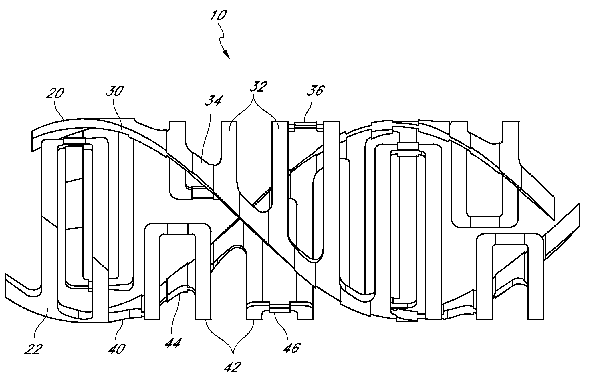
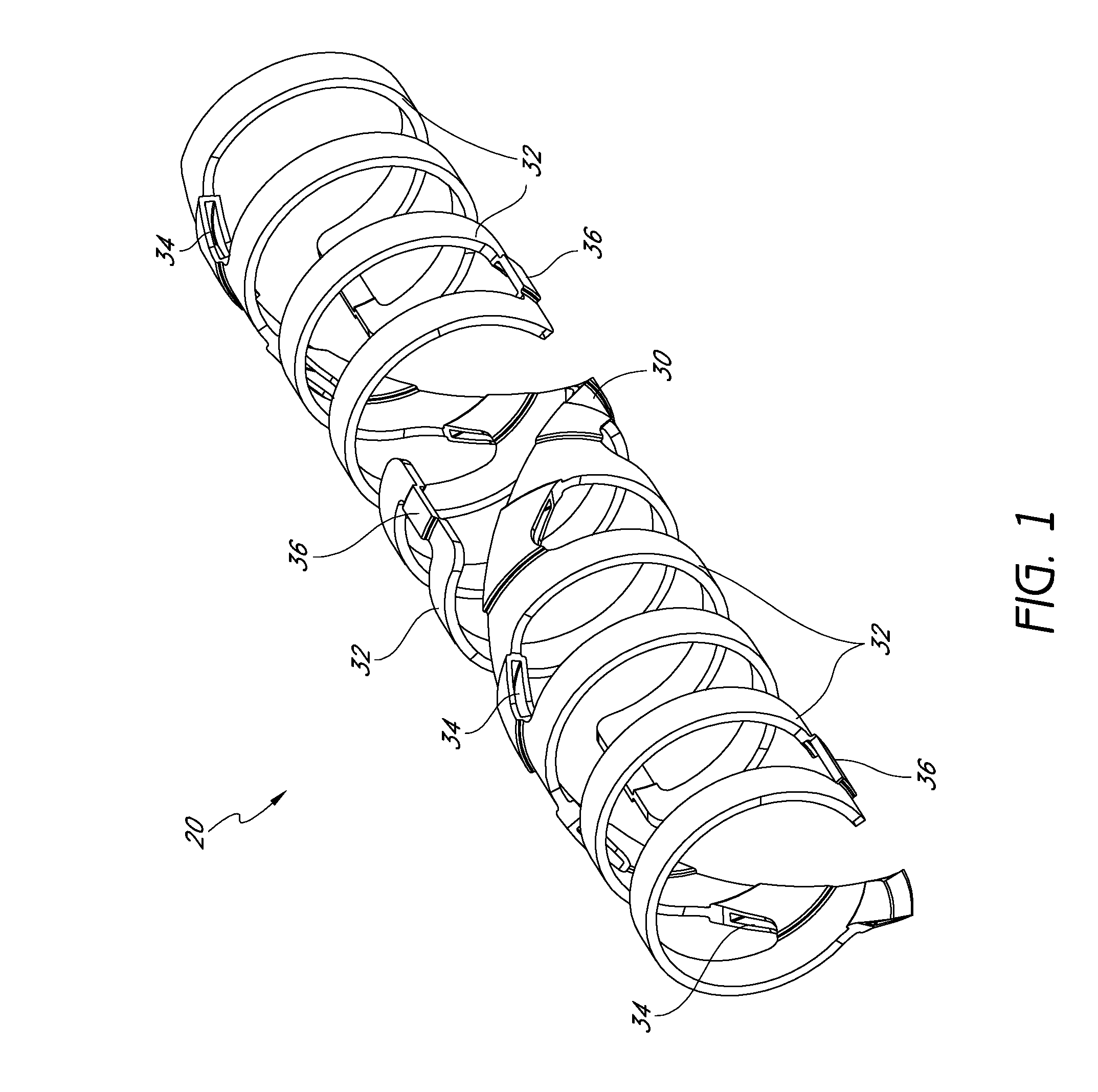
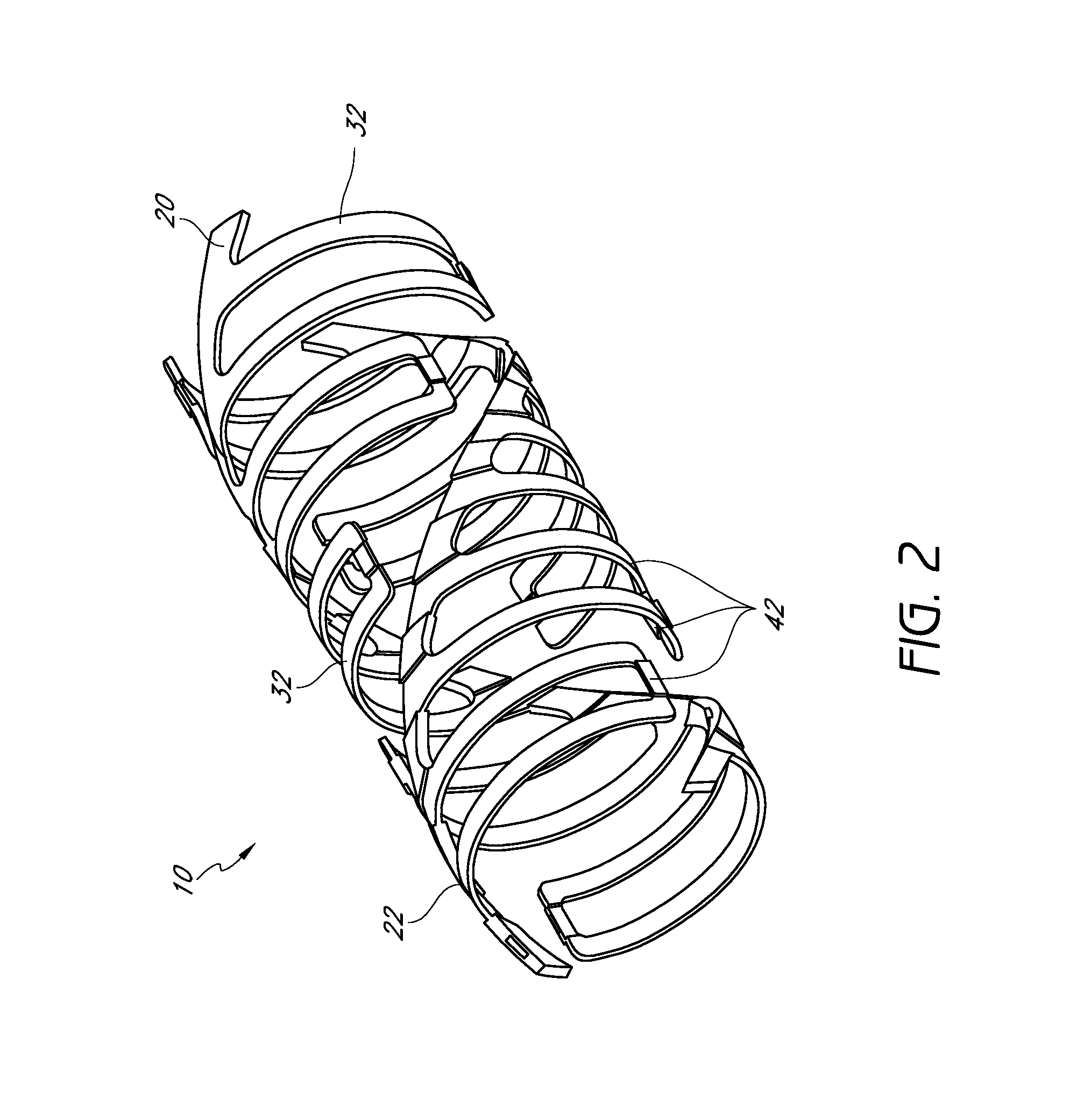
[0156]FIGS. 1-8 show conceptual views of embodiments of an expandable vascular device, prosthesis or stent in assembled and exploded orientations. The stent can be operative to move via translation and / or slide and lock movement. FIGS. 1-8 are intended to be conceptual in nature. Thus, the embodiments shown in FIGS. 1-8, as well as other embodiments of the stents disclosed herein, can incorporate structural elements, structural members, slide and lock mechanisms and other features that are discussed in further detail below with reference to further drawings as described in further detail herein.

[0157]Referring to FIGS. 1-5, a stent 10 is provided that can have a tubular form. These figures illustrate that the stent 10 can have a wall comprising a plurality of generally helically arranged linked radial elements or modules 20, 22. The stent 10 can have a through lumen which, along with the stent itself, can be expandable from a first diameter (Dlumen-collapsed or Dinner-collapsed) to ...


PUM


Abstract

An expandable slide and lock stent is provided that comprises a plurality of radial elements interconnected to form a tubular member. Each radial element can comprise a helical backbone and at least one elongate member extending from the helical backbone in a circumferential direction. Each backbone can have at least one slot that can be configured to receive an elongate member of an adjacent radial element.

Description

CROSS-REFERENCE TO RELATED APPLICATIONS[0001]This application claims the benefit of U.S. Provisional Application Nos. 61 / 104,683, filed Oct. 10, 2008, and 61 / 231,972, filed Aug. 6, 2009, the entireties of which are incorporated herein by reference.BACKGROUND[0002]1. Field of the Inventions[0003]The present inventions relate generally to expandable medical implants for maintaining support of a body lumen, and more specifically, to a uniform stent having improved mechanical and post-deployment dynamic capabilities.[0004]2. Description of the Related Art[0005]Various embodiments of vascular implants; such as stents, thrombus filters, and heart valves, are used in their various embodiments for medical applications. Of these vascular devices, one of the leading candidates as a stent device and structural component is the radially expandable and slidably engaged stent as disclosed in commonly owned U.S. Pat. Nos. 6,033,436; 6,224,626; and 6,623,521; the disclosures of which are hereby inc...

Claims


Application Information

Patent Timeline
Patent Type & Authority Patents(United States)
IPC IPC(8): A61F2/06A61F2/92
CPCA61F2/92A61F2/93A61F2230/0091A61F2220/0016B33Y80/00
Inventor SCHMID, ERICMORRIS, ANDREWWEIER, KEITHBONSIGNORE, CRAIGESSER, KEITHHOWARD, STEVEN C.DIPARI, JOSEPH A.
Owner REVA MEDICAL
Why Eureka
Try Eureka