Automatic fluid channel screen lock-unlock system

a technology of automatic locking and fluid channel, applied in the direction of separation process, sewage draining, ways, etc., can solve the problems of inability to block some items, many curb inlets have no effective means for blocking the entry of trash, maintenance personnel are under extreme pressure to mount an intensive and expensive effort to remove the blocking device, etc., to enhance the rigidity

Inactive Publication Date: 2011-05-31
NINO KHALIL IBRAHIM
View PDF60 Cites 33 Cited by
  • Summary
  • Abstract
  • Description
  • Claims
  • Application Information

AI Technical Summary

Benefits of technology

[0015]The present invention relates to a screen lock-unlock system for automatically locking and unlocking a screen that is installed (or, that is installable, if not already installed) within a fluid channel wherein the installed screen (i.e., the screen as installed within the channel) is rotatable relative to the channel from closed (a rotational position wherein the screen is orientated for blocking at least some trash from moving downstream past the screen) to open (a rotational position wherein the screen is orientated for allowing more trash, relative to what the screen allowed when it was closed, to move downstream past the screen). (References herein to “screen” are intended to include structural features incorporated into the screen for enhancing its rigidity, which move with the screen. A structural feature such as this might, for example, be in the form of a folded portion of the screen made by bending an edge of the screen to be perpendicular to the face of the screen (e.g., a bend resulting in the screen having a cross-sectional shape similar to the letter “L” in the vicinity of the bend), and / or a screen frame fixedly attached to the screen (such as a supporting frame secured to the screen around all or part of the screen's periphery).
[0019]According to one aspect of the system, it also includes a lock bar wherein the lock bar is rotatably attached (or, attachable if not already attached) to the screen support structure, preferably by being rotatably attached to an intermediate lock bar bracket that is fixedly attached (or, attachable if not already attached) to the screen support structure, and wherein the lock bar is rotatable by movement of the trigger within at least some part of the trigger's range of movement. Preferably, the lock bar is an elongated bar made of a strong rigid material, such as steel, and, also preferably, the lock bar is formed (such as by being bent, cast, molded, or made by securing separate parts together) into a shape that includes a bar front portion and a bar back portion, wherein the bar front portion and the bar back portion, as viewed from the side, are oriented at an angle relative to one another. (Preferably, the angle is a right angle such that a cross-sectional side view of the lock bar appears shaped like an “L” turned upside-down. Although, optionally, the angle may be other than 90 degrees or even zero.) The lock bar front portion is located, while the lock bar is in a locked position, for preventing (stopping) the closed installed screen from opening. This can be done by placing the bar front portion within, and therefore blocking, the rearward arc path of a screen blockable part, which may be fixed to or an integral part of the screen. (The blockable part is carried with the screen, in an arc path, as the screen rotates about the axis of the screen rotational connector, e.g., the screen rod). The blockable part preferably is in the form of a flange such as a flapper bracket flange extending laterally from the screen.
[0020]The trigger (which could be in the form of, for example, a trigger bar or cam fixed to the flapper rod, or a bent end portion of a flapper rod), is located sufficiently close to the lock bar for rotation of the trigger in response to rearward rotation of the flapper beyond a threshold release angle, to move the lock bar in a direction and amount needed for the forward end of the bar front portion to clear (move downward enough to be out of the rearward arc path of) the blockable part and thereby unlock the screen. (The threshold release angle can be any angle selected for making a particular installation of a screen that has, or will have, an embodiment of the present lock-unlock system connected to it. Presumably such a selection would be based on the installation environment and any operational requirements and / or specifications identified in advance for that installation. And, it is believed that the selected release angle for clearance of the blockable part can readily be determined by those skilled in the art based on the size and configuration of each of the affected parts utilized, and their relationships to one another, for any combination of an embodiment of the system with a screen and its screen support structure, as described and / or shown herein.) Notably, the system can be made to unlock a screen in response to the flapper rotating a fairly small amount from its at-rest position to reach its threshold release angle. (The at-rest position of the flapper being the position at which it comes to rest while the screen is locked closed and while the flapper is not being displaced by fluid and / or trash acting on it.) It is believed that embodiments can be made to operate effectively using a threshold release angle that is reached by the flapper rotating less than 15 degrees.
[0023]Preferably, the system also includes a lock bar counter-rotation limiter for blocking counter-rotation of the lock bar beyond its locking position (counter-rotation being rotation in a direction for moving the forward end of the bar front portion upwardly to its blocking position from a position wherein it was clear of the blockable part). Preferably, the lock bar bracket comprises the counter-rotation limiter, which, preferably, is the back edge of the lock bar bracket or may be (or include) a separate piece secured to the lock bar bracket. The counter-rotation limiter preferably would be located in the arc path of the bar back portion, wherein it would stop counter-rotational movement of the bar back portion at a position for placing the bar front portion in its blocking position. And, preferably, the bar back portion would rest against the counter-rotational limiter while the lock bar is in its locking position. For example, the lock bar bracket may have a vertically disposed back edge serving as a counter-rotation limiter that is located and shaped for stopping counter-rotation of the lock bar by stopping its bar back portion as described above, and for allowing positive rotation of the lock bar from its locking position by providing room for both the bar back portion and the bar front portion to move along their respective arc paths with positive rotation of the lock bar. (Positive rotation being rotation in a direction for moving the forward end of the bar front portion downwardly away from its blocking position to clear the blockable part, which generally would be the opposite direction from the counter-rotation direction.) Also, preferably, at least part of the bar back portion is wider than the bar front portion, for enabling the lock bar bracket to be placed at a location wherein it is inside the arc path of the wider part of the bar back portion while being outside the arc path of the narrower bar front portion, thus enabling the back edge of the lock bar bracket to serve as the counter-rotation limiter.
[0026]And, preferably, the flapper has a flapper main section and a flapper bottom section wherein the bottom section includes the flapper bottom, with at least part of the bottom section (e.g., the bottom edge) located forward of the main section, for at least part of the bottom section to intercept downwardly flowing impact fluid at an angle greater than the angle between the main section and such fluid. Also preferably, the flapper additionally has a flapper top section wherein the top section includes the flapper top, with the portion of the flapper top attached to the flapper rotational connector being located forward of at least some of the main section (preferably, forward of the flapper's center of gravity), for increasing the angle at which at least part of the main section will intercept downwardly flowing impact fluid. Thus, preferably, where the flapper has such a bottom section and / or a top section oriented differently from its main section, the orientations of the bottom and top sections are selected for increasing—relative to a flapper without bottom and / or top section(s) oriented differently from its main section—the area and angle of impact by flow-through fluid against the main and / or bottom section(s) of the flapper, thus increasing the effect on the flapper of a given depth and rate of flow-through fluid, particularly flow-through fluid that is descending (e.g., from the upper portion of the screen, as might be the case if the lower front of the screen is clogged with trash forcing incoming fluid to flow over the clogged portion) when it impacts the flapper.

Problems solved by technology

Of course, any given screen may be unable to block some items of trash with a dimension larger than the screen's openings, particularly where those items are elongated, compressible, and / or flexible enough to sometimes pass through the openings.
It may be observed that many curb inlets have no effective means for blocking the entry of trash.
These heavy flow periods often commence unexpectedly or on very short notice and, in some geographical areas, frequently.
Thus, installation of most previously proposed blocking devices for curb inlet channels would put maintenance personnel under extreme pressure to mount an intensive and expensive effort to remove the blocking devices whenever heavy flow periods occur.
Removal of such blocking devices generally requires personnel to expend substantial time and, in some cases, to use expensive equipment in order to access and remove the connecting means and the devices.
Nevertheless, such removal is necessary because the trash accumulated at the face of the blocking devices significantly impedes the large volume of fluid that is flowing into the drain system, thus causing a damming effect.
Also, the blocking devices will continue to block and accumulate the additional trash that is being carried with the large volume of fluid, exacerbating the damming effect.
Therefore, unless agencies that have responsibility for street and highway maintenance and / or flood control either forgo the benefits of having blocking devices or expend large sums for personnel and equipment to immediately remove the blocking devices every time a heavy flow period threatens or commences, the accumulations at the entrances to their drainage systems are very likely to cause substantial flooding.
And, further, that the prior devices made of metal or other non-plastic material are not particularly suitable for installation within a curb inlet channel and generally do not, without human assistance, clear the accumulated trash during periods of heavy flow.
It has also been contended that attaching the heavy components of metal blocking devices with bolts anchored within the inlet or catch basin will weaken and over-stress that structure.
However, the advantages also appear to be limited by those materials.
The strength, flexibility and elasticity of plastics and adhesives may be adversely affected by repeated flexing and extended exposure to environmental conditions such as sun, air, water, and extreme temperature variations (ranging from above 100 degrees Fahrenheit to well below 0 degrees Fahrenheit in some geographical areas).
A secure bond may be difficult to achieve or maintain in circumstances where the surface (generally made of concrete) suffers from irregularities, impurities, or mechanical weaknesses; and, if achieved, may be difficult to remove without some damage to the surface or the device.
And, if a very inelastic material is used, the device may not open fully even when the initial resistance is overcome by a large pressure (the degree of resistance in such materials often increasing with the degree of flexure), which is generally when full opening is most desired.
Such a device, therefore, provides no effective means of control to assure the blockage is maintained when that is most desirable and released when that is most desirable.
It also appears that those efforts did not address or suggest a practical and economical solution to the problem of trash accumulation and blockage during heavy flow periods when the passage of fluid needs to be maximized.

Method used


Image

  • Automatic fluid channel screen lock-unlock system
  • Automatic fluid channel screen lock-unlock system
  • Automatic fluid channel screen lock-unlock system

Examples


Embodiment Construction

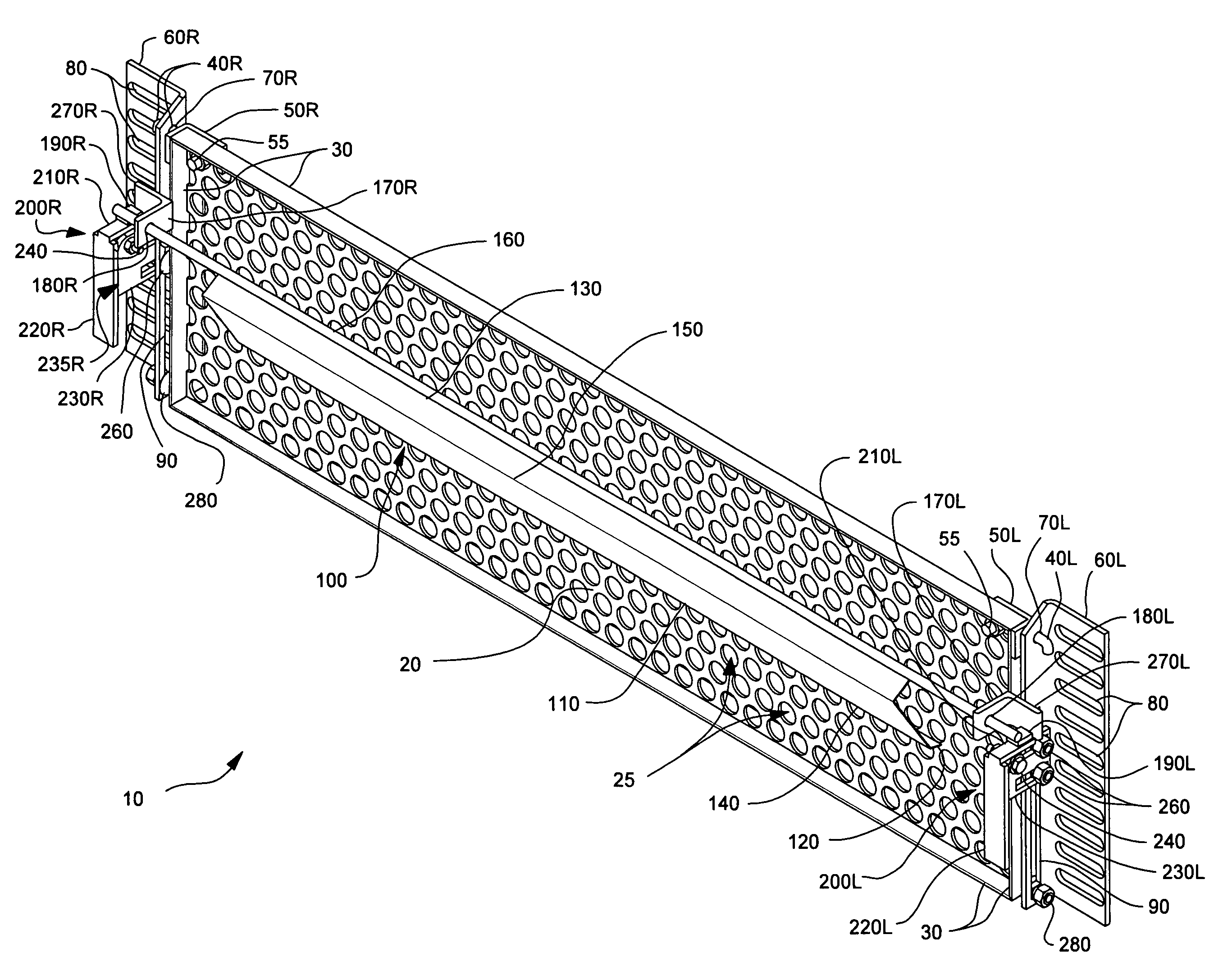
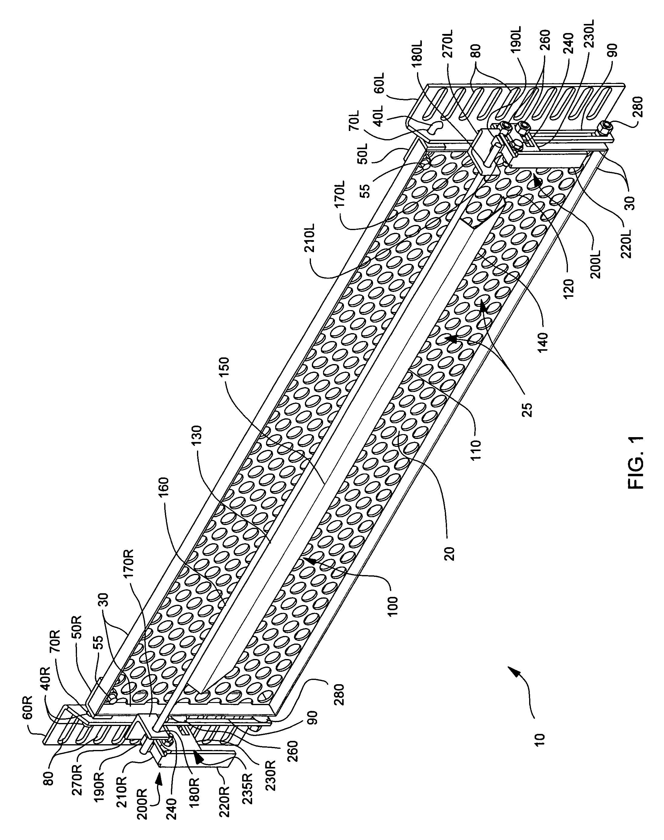
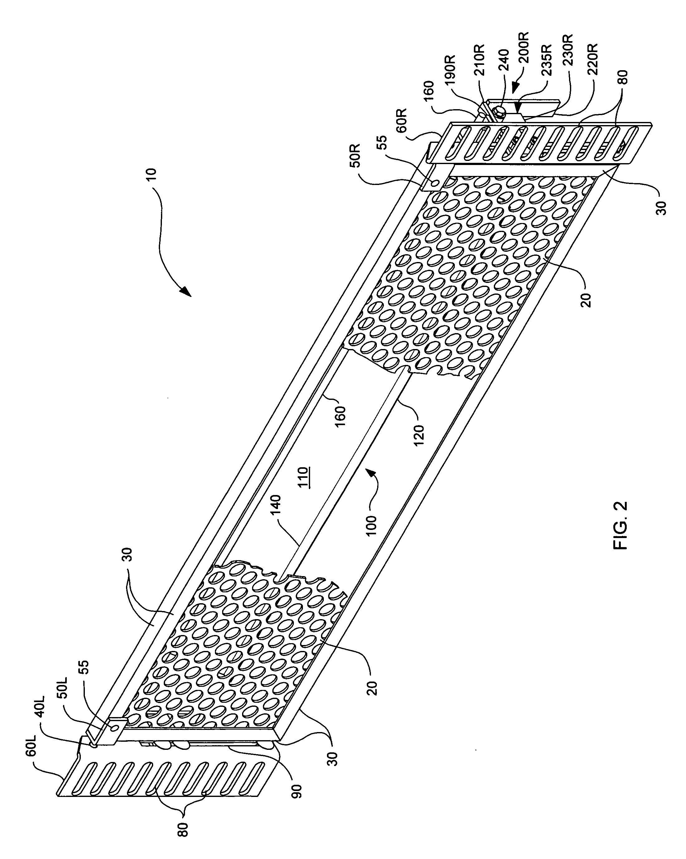
[0041]As used herein, unless expressly stated otherwise, the following terms have the definitions referred to or specified in this paragraph. The term “embodiment” means embodiment of the present invention. The term “trash” has the meaning given to it in the BACKGROUND OF THE INVENTION section, with the predetermined size being whatever size of trash the user of the screen wishes to specify for being blocked from passing to the downstream side of the closed installed screen (with due consideration to the fact that some trash that is non-rigid or that has a dimension smaller than the predetermined size might not be blocked). The terms “left” and “right” are intended to mean such directions as viewed from the upstream side of the blocker. The term “front” means the upstream side and the term “back” means the downstream side. The terms “vertical” and “horizontal” are intended to include directions that are substantially vertical and substantially horizontal, respectively. The term “pre...


PUM

PropertyMeasurementUnit
angleaaaaaaaaaa
threshold release angleaaaaaaaaaa
pressureaaaaaaaaaa

Abstract

The present invention relates to a screen lock-unlock system for automatically locking and unlocking a screen that is within a fluid channel wherein the screen is rotatable relative to the channel from closed to open. The system includes an actuator comprising a flapper and a trigger, wherein the flapper is rotatably connectable to the back of the screen. The flapper is operably connected to the trigger for moving the trigger. And, the system is further summarized, according to one aspect, as follows. It includes a lock bar wherein the lock bar is rotatably attachable to a screen support structure, the lock bar being rotatable by movement of the trigger. The lock bar intercepts the rearward arc path of a blockable part (such as a flange extending laterally from the screen). The flapper is located and oriented with respect to the closed screen for at least part of the flapper to be rotatable in response to pressure from impact fluid. The trigger is located sufficiently close to the lock bar for rotation of the trigger to move the lock bar in a direction and amount needed for at least part of the lock bar to clear the blockable part, allowing the screen to open in response to pressure against the front of the screen. The screen is rotatable toward a closed position in response to the diminishment of the pressure against the front of the screen. And, the lock bar is biased in a counter-rotation direction (by part of the lock bar and / or another biasing device) to at least help hold the lock bar in and / or return it to a locked position.

Description

CROSS-REFERENCE TO RELATED APPLICATIONS[0001]This application is derived from U.S. Provisional Application No. 61 / 048,167, filed Apr. 25, 2008, and claims the benefit of said Provisional Application.BACKGROUND OF THE INVENTION[0002]The present invention relates to a system of mechanical components arranged to cooperate with each other for locking and unlocking a rotatable screen that is located for intercepting the flow of fluid through a channel such as a catch basin curb inlet channel. More particularly, the present invention relates to such a system that holds the screen closed to impede the movement of fluid-borne trash under low fluid-flow conditions but automatically releases the hold for allowing the screen to rotate open in order to permit an increased volume of the fluid (and trash carried with it) to move downstream past the screen during high fluid-flow conditions, and then automatically resumes its hold when the screen re-closes upon dissipation of the high fluid-flow co...

Claims


Application Information

Patent Timeline
Patent Type & Authority Patents(United States)
IPC IPC(8): E03F5/14
CPCE03F1/00E03F5/046E03F5/0404
Inventor NINO, KHALIL IBRAHIM
Owner NINO KHALIL IBRAHIM
Why Eureka
Try Eureka