
Angled stabs for a busway plug in unit

a technology of angled stabs and busway, which is applied in the direction of connecting contact member materials, conductors, single bars/rods/wires/strips, etc., can solve the problems of uneven thickness around corners and bends, time-consuming and laborious epoxy insulation, and uneven thickness of epoxy insulation, so as to improve the thermal efficiency of the busway system and eliminate air gaps

Active Publication Date: 2011-05-31
SCHNEIDER ELECTRIC USA INC
View PDF7 Cites 13 Cited by
  • Summary
  • Abstract
  • Description
  • Claims
  • Application Information

AI Technical Summary

Benefits of technology

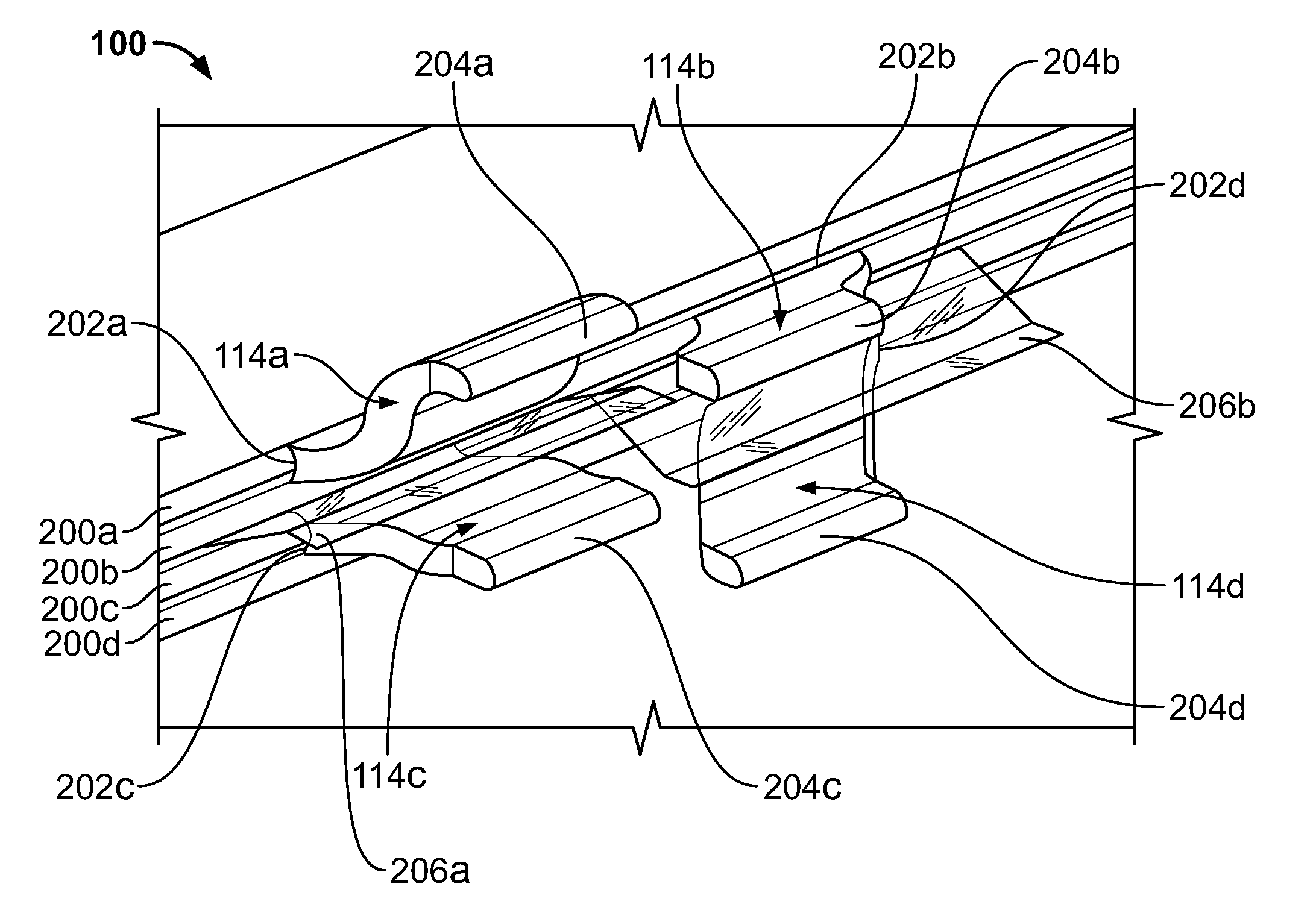
The present invention is a busway system that can be easily installed in existing equipment without the need for redesign. The system includes a housing and multiple busbars arranged in a flat stacked configuration. The busbars are positioned at least in part within the housing and include a first busbar, a second busbar, a third busbar, and a fourth busbar. The system also includes at least one plug-in opening with a plurality of uninsulated stabs, including a first pair of uninsulated stabs and a second pair of uninsulated stabs. The first pair of uninsulated stabs includes a first upper stab and a first lower stab, while the second pair of uninsulated stabs includes a second upper stab and a second lower stab. The uninsulated stabs are angled towards each other to improve thermal efficiency and eliminate air gaps in the design. The technical effects of this invention include improved thermal efficiency, simplified installation, and reduced costs.

Problems solved by technology

Some current busbars are required to include insulated stabs because the respective configurations cannot meet the UL requirement of providing a 2-inch over-surface clearance or a 1-inch over-air clearance.
However, epoxy insulation is labor intensive, time consuming, and expensive.
Furthermore, epoxy insulation may have cracks and uneven thickness around corners and bends.

Method used


Image

  • Angled stabs for a busway plug in unit
  • Angled stabs for a busway plug in unit
  • Angled stabs for a busway plug in unit

Examples


Embodiment Construction

[0024]Although the invention will be described in connection with certain preferred embodiments, it will be understood that the invention is not limited to those particular embodiments. On the contrary, the invention is intended to include all alternatives, modifications and equivalent arrangements as may be included within the spirit and scope of the invention as defined by the appended claims.

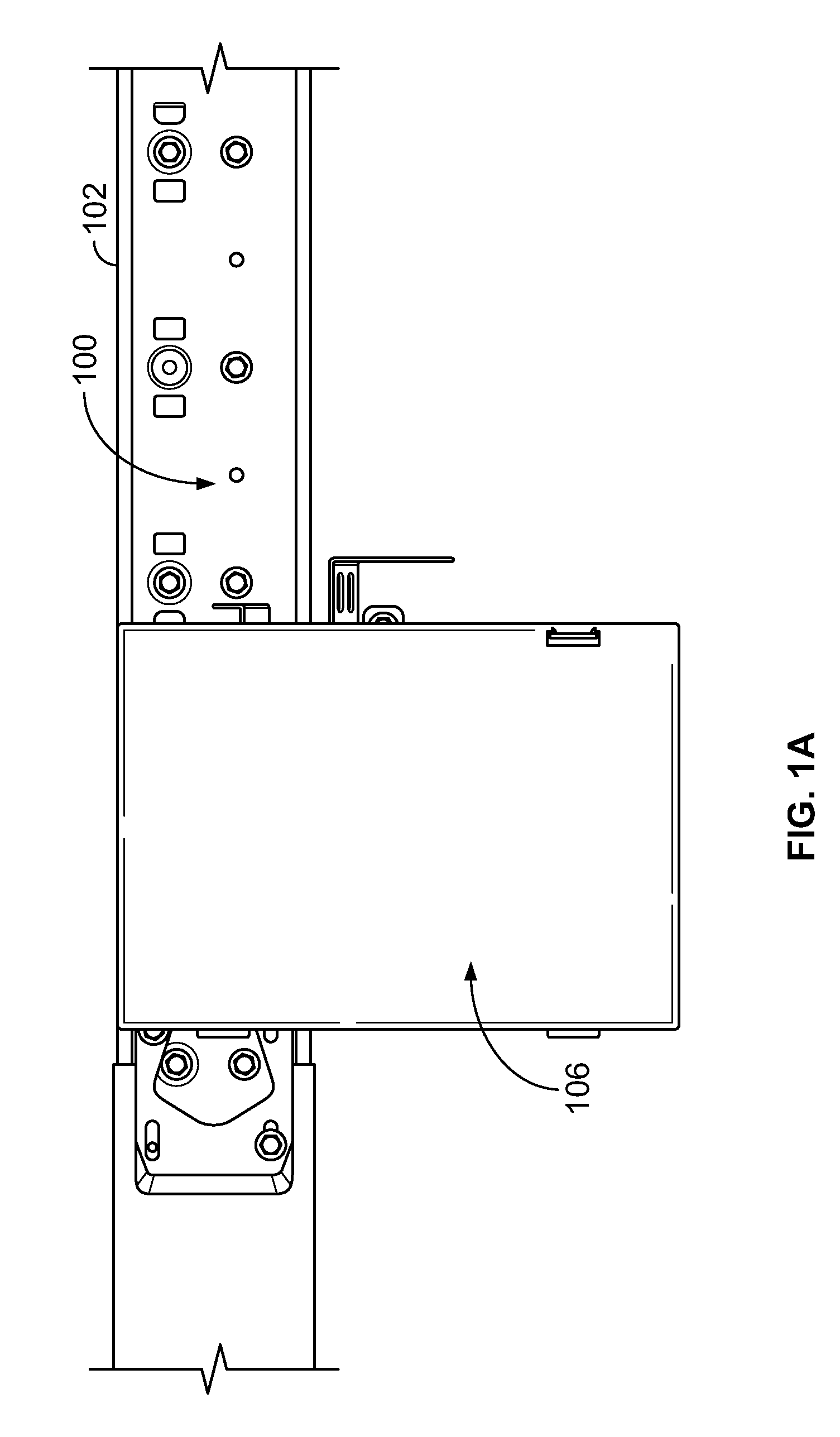
[0025]Referring to FIG. 1A, a busway system 100 includes a busway housing 102 in which one or more plug-in openings 104 (illustrated in FIG. 1B) are located. A plug-in unit 106 is mounted to the busway system 100 in a horizontal application, according to one embodiment.

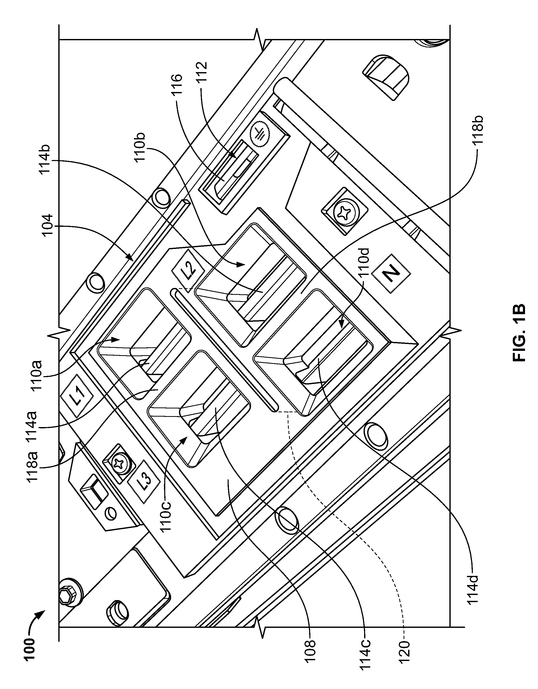
[0026]Referring to FIG. 1B, the plug-in opening 104 includes a molded plastic base 108 having a plurality of stab apertures 110a-110d and a ground aperture 112. Each of the stab apertures 110a-110d has a corresponding uninsulated stab 114a-114d extending from a respective busbar (shown in FIG. 2 as busbars 200a-200b) of the bus...


PUM


Abstract

A busway system includes a plurality of busbars arranged in a flat stacked configuration. The system further includes at least one uninsulated stab having a base in direct contact with one of the busbars at a first length portion of the busbars. The stab also has a tip extending away from the base and angled at the length of the busbars such that the tip is positioned at least in part at a second length portion of the busbars. The stab is insulated from other stabs via one or more of a MYLAR® sheet and a wall of a plug-in opening base.

Description

FIELD OF THE INVENTION[0001]This invention is directed generally to a busway system, and, more particularly, to a busway with angled stabs separated by an insulation sheet.BACKGROUND OF THE INVENTION[0002]Busway electrical distribution systems are well known in the art of electrical distribution. Busway systems are comprised of a number of factory assembled sections each including a number of individually insulated generally flat electrical conductors or busbars stacked one upon another and enclosed within a housing which provides protection and support for the busbars. The busway sections include one or more plug-in openings having a plurality of conductive stabs. In general, the plug-in openings are openings provided through the housing of the busway system at each of a plurality of power tap-off sections to expose conductive material of the busbars for connection with an appropriate connecting jaw. A plug-in unit, which is used to tap off power from the busway, is attached to the...

Claims


Application Information

Patent Timeline
Patent Type & Authority Patents(United States)
IPC IPC(8): H02G5/00
CPCH02G5/08
Inventor RAMSEY, JIM
Owner SCHNEIDER ELECTRIC USA INC
Learn More