
Method and arrangement for performing triggering and timing of triggering

a technology of triggering and timing, applied in the direction of distance measurement, pulse technique, instruments, etc., can solve the problems of inability to convert significant errors in the measurement of the time between the transmitted pulse and the received pulse, and inability to achieve the effect of converting a pulse to bipolar, so as to improve the measurement accuracy of the solution and the determination of the exact triggering momen

Active Publication Date: 2011-05-31
UNIV OF OULU
View PDF13 Cites 2 Cited by
  • Summary
  • Abstract
  • Description
  • Claims
  • Application Information

AI Technical Summary

Benefits of technology

[0007]The object of the invention is to provide an improved method and an arrangement implementing the method so that the error made in the triggering remains small.
[0014]The method and arrangement of the invention provide a plurality of advantages. In triggering, the walk error remains small, which improves the determination of an exact triggering moment. This, in turn, improves the measurement accuracy of the solution presented.

Problems solved by technology

However, the problem is that the amplitude of the received pulse usually varies strongly for instance according to the distance and the reflectivity of the reflecting object.
The reception moment, in turn, changes as the amplitude of the received pulse changes, i.e. a so-called walk error occurs in the triggering performed in the measurement causing even significant errors in the measurement of the time between the transmitted pulse and the received pulse.
A walk error occurs because of the unipolar optical pulse, and, characteristically, the unipolar pulse has no such feature that would enable triggering and timing without walk error.
However, converting a pulse to bipolar does not succeed when the amplitude of an electrical pulse is cut in amplifiers preceding the timing comparator.
However, the problem associated with triggering is not solved this way, but a new problem is created, i.e. that the delay caused to the electrical pulse by the AGC circuits varies according to the amplification of the AGC circuit, i.e. the dynamics are limited in a given measurement error range.
The technology is also complicated.
This causes problems.
Furthermore, the magnitude of the timing error depends on the rate of rise of the pulse, etc.
The timing error reaches its peak when one or more amplifiers are saturated.
In all, the problem in edge detection is insufficient accuracy.

Method used


Image

  • Method and arrangement for performing triggering and timing of triggering
  • Method and arrangement for performing triggering and timing of triggering
  • Method and arrangement for performing triggering and timing of triggering

Examples


Embodiment Construction

[0022]The solution presented is applicable for instance in a distance measurement device based on the propagation time of an optical pulse or in nuclear technological measurement devices, without, however, being restricted thereto.

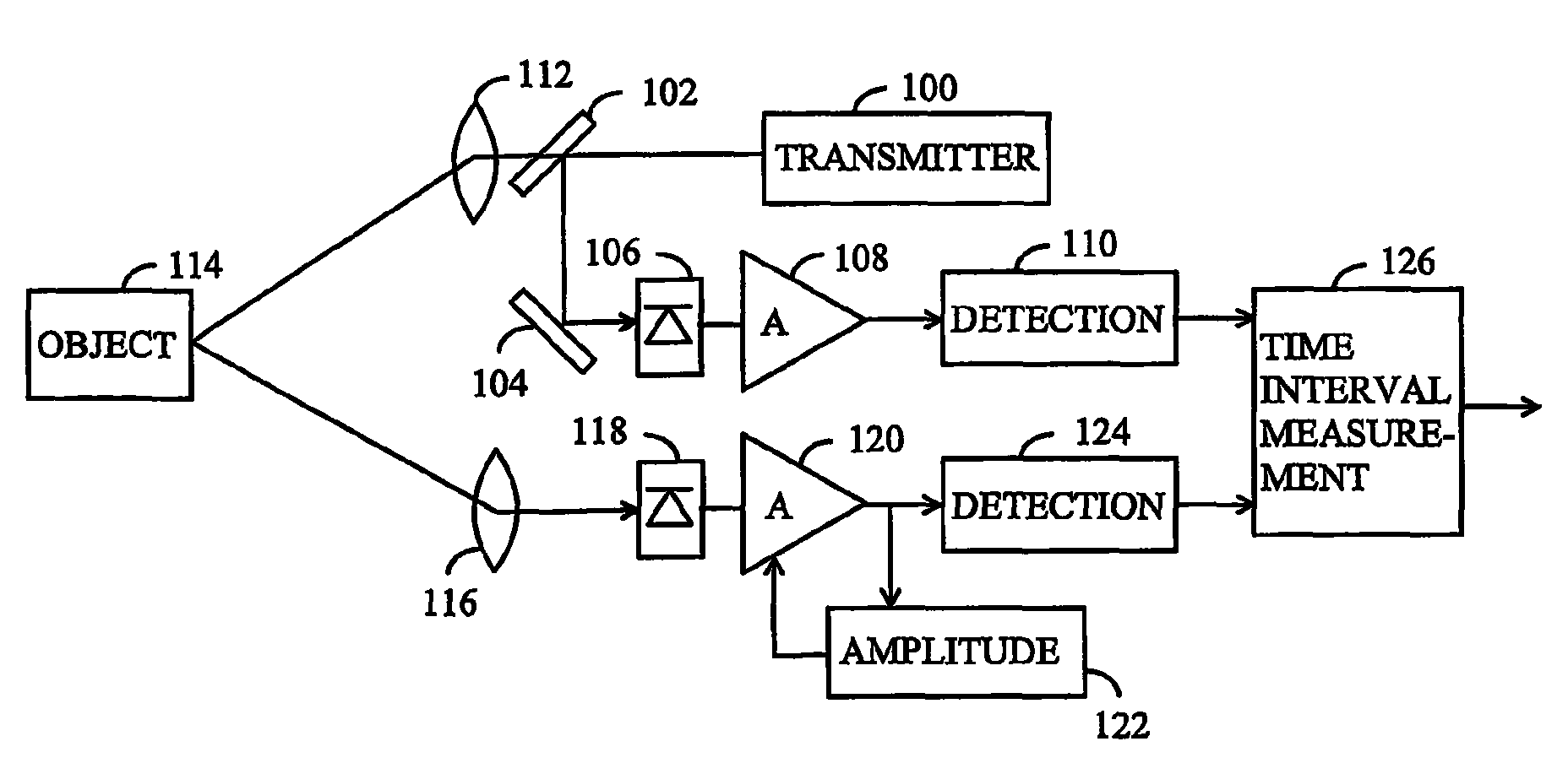
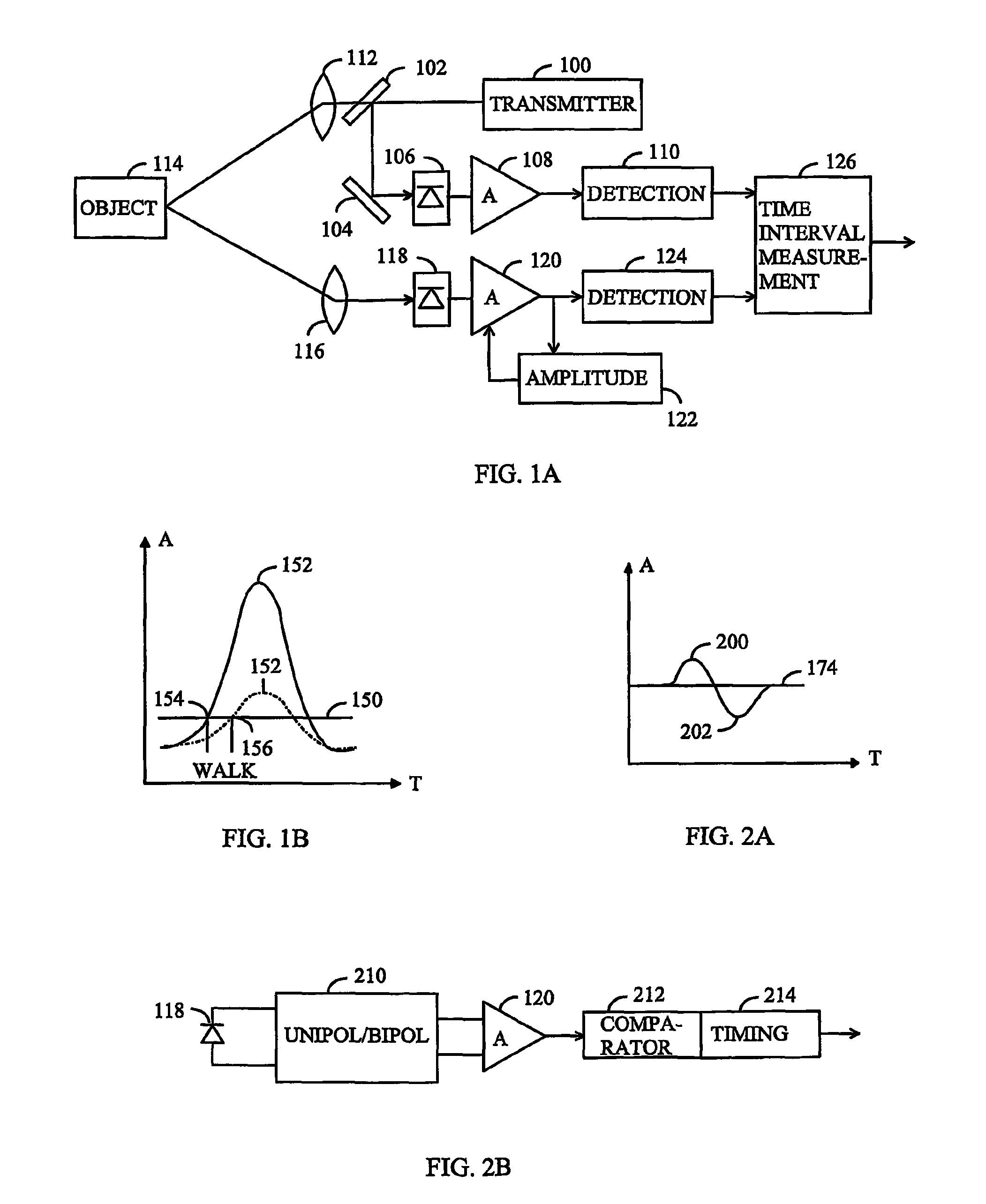
[0023]Let us now study a distance measurement device based on the propagation time of an optical pulse by means of FIG. 1. In the present application, optical radiation refers to electromagnetic radiation at wavelengths between 40 nm to 1 mm. The distance measurement device comprises an optical pulse transmitter 100, which may be a laser, led or other device for transmitting optical pulses. The kind of device involved is not essential to the solution presented. The duration of an optical pulse may be for instance some nanoseconds (5 ns to 10 ns), but the solution presented is not either restricted to the duration of the pulse. A pulse transmitted by the transmitter 100 is directed to a detector 106 by using a partially transparent mirror 102 and mirror 104...


PUM


Abstract

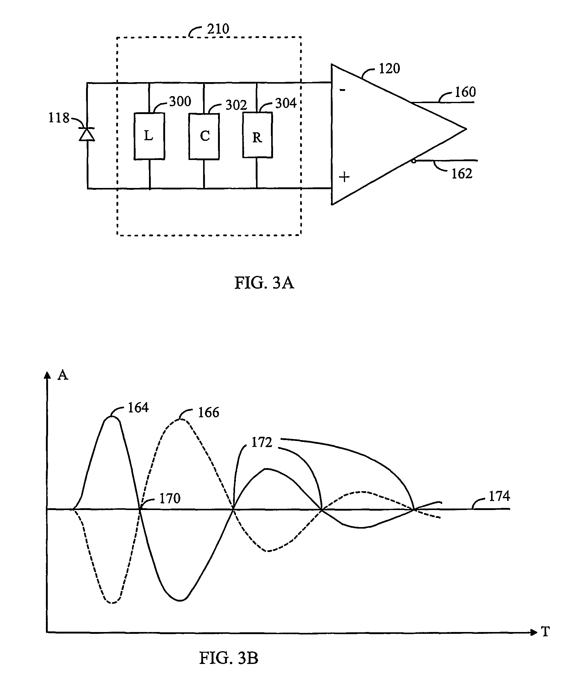
The invention relates to a method and an arrangement for performing triggering and for determining a triggering moment. In the solution, a unipolar electrical pulse of a detector (106, 118) is converted between the detector (106, 118) and a first amplifier (108, 120) succeeding the detector into at least one bipolar electrical oscillation. The bipolar electrical oscillation is amplified with at least one amplifier (108, 120) and triggering is performed at a zero level between the extreme values of the bipolar electrical oscillation. In addition, a triggering moment is determined, at which the amplified bipolar electrical oscillation crosses the zero level between its extreme values.

Description

FIELD[0001]The invention relates to performing the triggering of a unipolar pulse and the timing of the triggering.BACKGROUND[0002]Triggering from a unipolar pulse in the same way at different pulse amplitude values is important in many technical applications. For example, in a distance measurement technique based on the propagation time of an optical pulse, the time-of-flight of a pulse is determined based on the difference between the transmission and reception moments of the pulse. The timing of the transmission and reception moments is measured by triggering a timing comparator by means of the optical pulse.[0003]The transmission moment is determined by reflecting a small part of the optical pulse to be transmitted, to a detector, which converts the optical pulse into an electrical pulse that is amplified in a preamplifier. For instance in constant threshold detection, the transmission moment is determined as the moment when the leading edge of an amplified electrical pulse exce...

Claims


Application Information

Patent Timeline
Patent Type & Authority Patents(United States)
IPC IPC(8): G01C3/08G01S7/487G01S17/14H03K5/125H03K5/1534H03K5/1536
CPCG01S7/487G01S17/105H03K5/1536H03K5/1534H03K5/125G01S17/14
Inventor KOSTAMOVAARA, JUHAPALOJARVI, PASIPEHKONEN, JANI
Owner UNIV OF OULU
Learn More