
Clock alias for timing analysis of an integrated circuit design

a timing analysis and integrated circuit technology, applied in the field of integrated circuit design timing analysis, can solve the problems of time-consuming and labor-intensive process for manually defining duplicate clocks that mimic other real clocks, and not being able to solve the problem of not being able to solve the problem of inability to accurately identify the time of the clock,

Inactive Publication Date: 2012-08-09
GLOBALFOUNDRIES INC
View PDF1 Cites 0 Cited by
  • Summary
  • Abstract
  • Description
  • Claims
  • Application Information

AI Technical Summary

Benefits of technology

The patent describes a mechanism for analyzing the timing of a circuit design and eliminating the need for manual creation of duplicate clocks. This mechanism uses a timing analysis to define a clock alias that correlates to a real clock in the design. This allows the designer to reference the real clock in the design without needing to manually modify the original assertion. The mechanism also generates a duplicate clock that has the same attributes as the real base clock and prevents errors when setting up the duplicate clock to match the base clock. This reduces the risk of manual errors and simplifies the process of updating the clock attributes as the design progresses. Overall, this mechanism improves the efficiency and accuracy of the circuit design process.

Problems solved by technology

Static timing analysis generally takes into account best-case and worst-case delays of various circuit elements, thereby generating a list of problems that need to be corrected.
This can cause problems when two parts of the same design expect the same clock, but under different names.
This is not a viable solution because of the time required to rewrite all of the existing user assertions.
However, it is common to have many hundreds of clocks in a design, which puts a significant burden on a designer to manually create many duplicate clocks that mimic the behavior of many other clocks.
In addition, the process for manually defining duplicate clocks that mimic other real clocks is time-consuming and prone to user errors.

Method used


Image

  • Clock alias for timing analysis of an integrated circuit design
  • Clock alias for timing analysis of an integrated circuit design
  • Clock alias for timing analysis of an integrated circuit design

Examples


Embodiment Construction

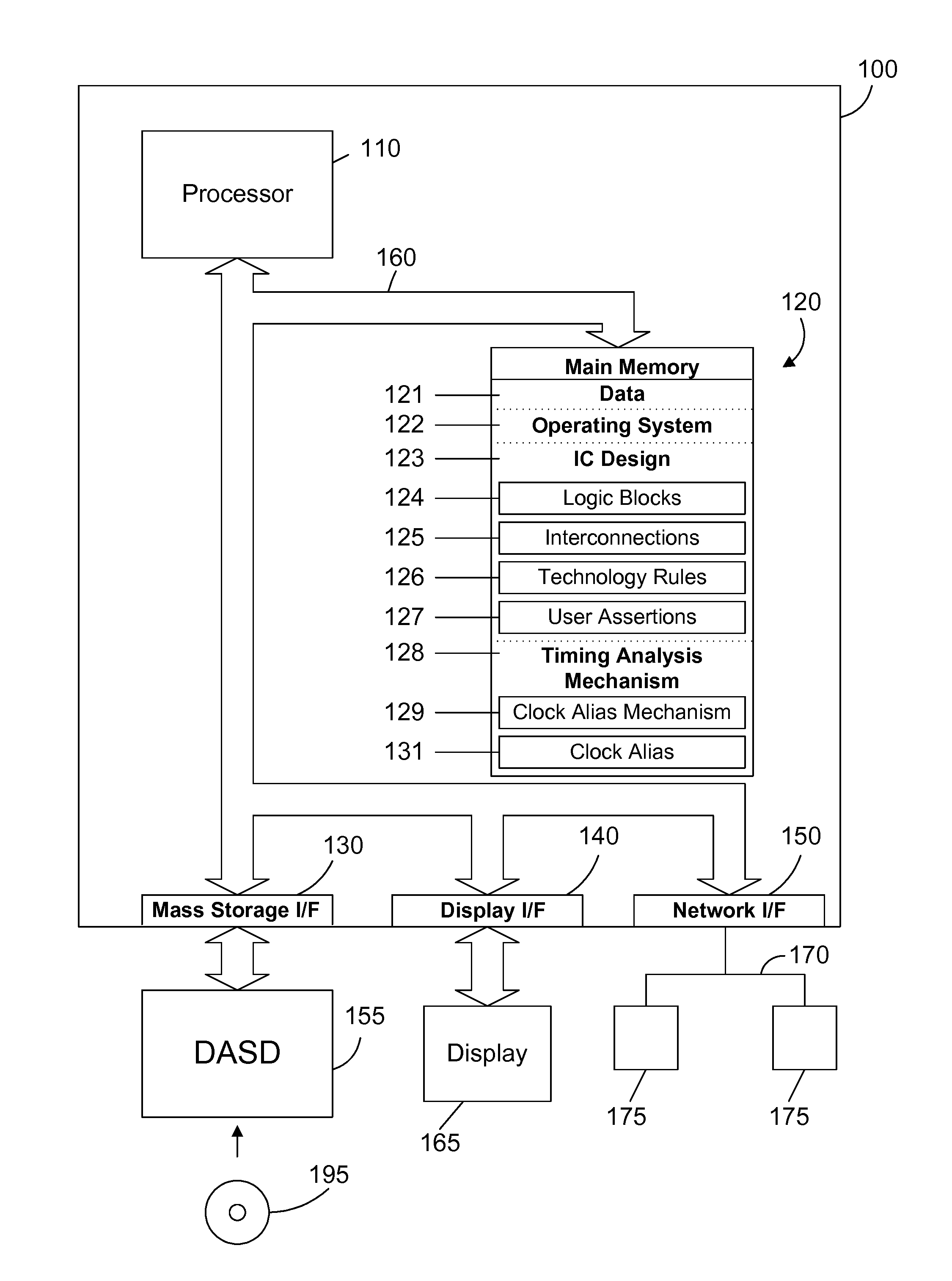
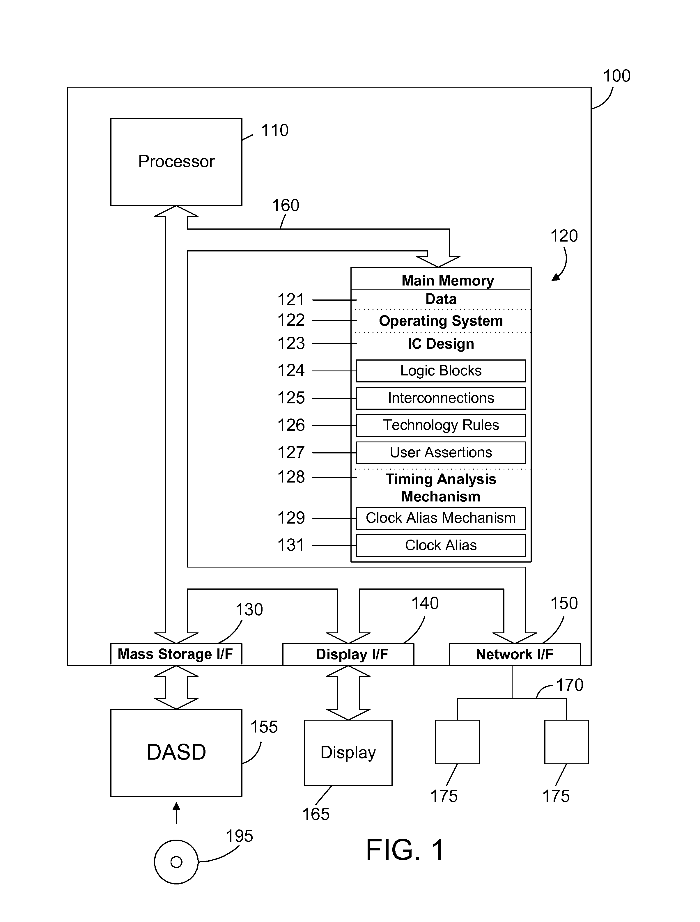
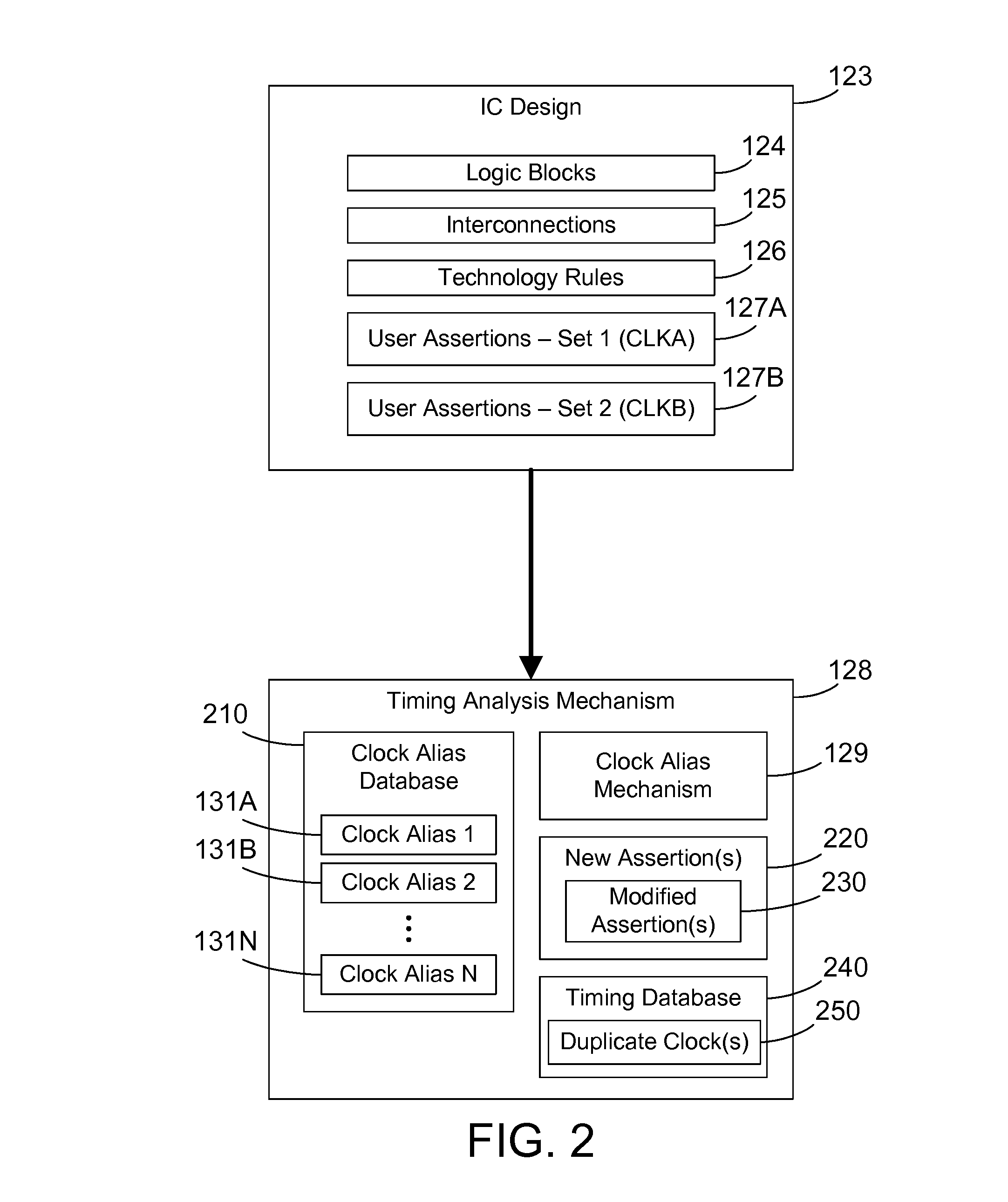
[0019]The claims and disclosure herein provide a timing analysis mechanism that allows defining one or more clock aliases. The need for a clock alias arises when a design includes different labels for what should be the same clock. This can happen, for example, when a logic block from a third party is incorporated into a design, and the assertions provided by the third party are in terms of clock labels in the logic block, which may have different clock names that the rest of the design. Clock aliases are used to define a clock in terms of a real clock in the system. In a first implementation, the clock alias causes a user assertion that references the clock alias to be modified to generate a new user assertion that refers instead to the real clock. The new user assertion is then processed. This allows the existing user assertions provided by the third party to be used without the designer having to manually rename the clock names in the existing user assertions and without generati...


PUM


Abstract

A timing analysis mechanism allows defining a clock alias that correlates a clock that is not present in an integrated circuit design to a real clock in the integrated circuit design. In a first implementation, when an existing user assertion references a clock alias, the timing analysis mechanism generates a new user assertion that references the real clock specified in the clock alias. The new user assertion is then used in the timing analysis and the existing user assertion is not. In a second implementation, when an existing user assertion references a clock alias, the timing analysis mechanism generates a duplicate clock in the timing database, preserving all its attributes, and then passes the assertion using the alias name as well as any assertions using the corresponding real clock name to the timing engine to be used in the timing analysis.

Description

BACKGROUND[0001]1. Technical Field[0002]This disclosure generally relates to integrated circuits, and more specifically relates to timing analysis of integrated circuit designs.[0003]2. Background Art[0004]The proliferation of modern electronics is due in large part to the development of the integrated circuit. Integrated circuits allow many different circuit elements to be implemented on a single chip. As technology advances, the number of circuit elements on a chip of a given size increases, enhancing the performance and reducing the cost of integrated circuits.[0005]The design of integrated circuits is typically performed in three stages. The first stage is logic design, wherein the desired operation of the integrated circuit is defined. The second stage is logic synthesis, wherein the desired operation is translated into the required circuit elements for a given technology. The third stage is physical design, which assigns the placement of these elements and routing which create...

Claims


Application Information

Patent Timeline
Patent Type & Authority Applications(United States)
IPC IPC(8): G06F17/50
CPCG06F17/5045G06F17/5031G06F30/3312G06F30/30G06F30/3315
Inventor AMUNDSON, MICHAEL D.DARSOW, CRAIG M.
Owner GLOBALFOUNDRIES INC
Learn More