Clip retainer

a retainer and clip technology, applied in the direction of snap fasteners, buckles, transportation and packaging, etc., can solve the problems of difficult assembly, difficult to meet design requirements, and difficult to assemble, so as to achieve simple structure and reliable use

Inactive Publication Date: 2011-06-07
YANFENG AUTOMOTIVE TRIM SYST CO LTD +2
View PDF14 Cites 31 Cited by
  • Summary
  • Abstract
  • Description
  • Claims
  • Application Information

AI Technical Summary

Benefits of technology

[0007]An object of the present invention is to provide a new clip retainer which can solve the problems that conventional clip retainers have complex structures, the operating force of assembling and disassembling of clip is difficult to be controlled, and conventional clip retainer are easy to lose efficacy during assembly and disassembly.
[0010]The clip retainer with the structure described above can meet the requirements of small slide-in force and large slide-out force of the clip. Further, the clip retainer has a simple structure, can produce repeated insertion and extraction deformation, and is very reliable to use.

Problems solved by technology

However, this kind of structure cannot meet the design requirements of small slide-in force and large slide-out force of the clip, which causes that the force of assembling the clip is great and the assembling is difficult.
However, the knuckle features are also difficult to meet the design requirements of small slide-in force and large slide-out force of the clip.
Furthermore, during insertion and extraction of the clip, the knuckle features are bent repeatedly, so plastic is easy to lose efficacy.
Since the clip retainers are integrated on automotive door interior trimming panel bodies, once the clip retainers lose efficacy, the whole door interior trimming panel assemblies have to be abandoned.

Method used


Image

  • Clip retainer
  • Clip retainer
  • Clip retainer

Examples


Embodiment Construction

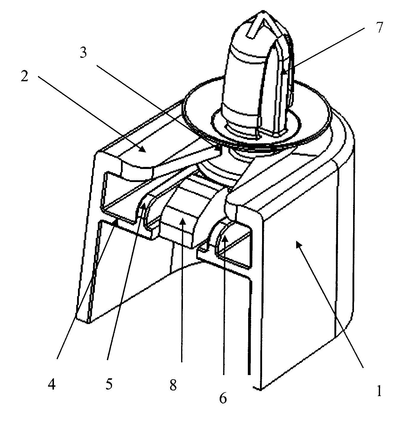
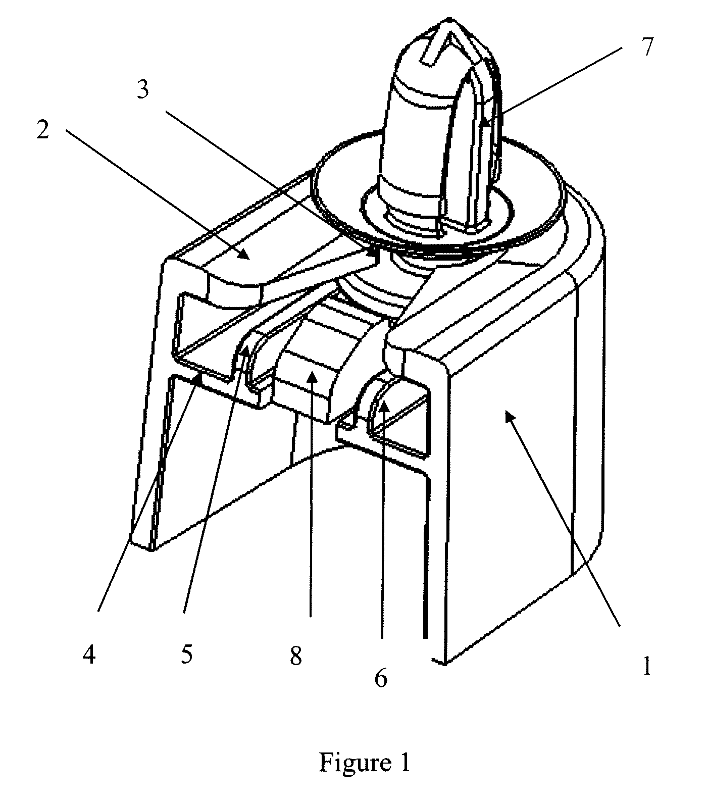
[0013]To further understand functions and features of the present invention, please refer to the detailed description of the preferred embodiment related to the present invention according to FIG. 1 and FIG. 2.

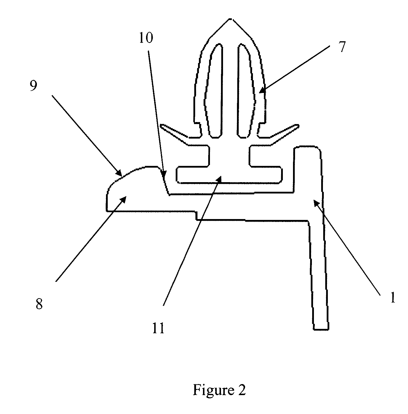
[0014]As shown in FIG. 1 and FIG. 2, a clip retainer 1 of the present invention has a groove 3 formed in a top surface 2 thereof and two stopping ribs 5, 6 formed on a bottom surface 4 thereof. Under the combined action of the top surface 2, the groove 3 and the stopping ribs 5, 6, a flange 11 of a clip 7 is clamping in the clip retainer 1.

[0015]The clip retainer 1 further has a barb 8 formed between the two stopping ribs 5, 6 on the bottom surface 4 thereof. Since the clip retainer 1 is a plastic member with a certain amount of elastic deformation, the barb 8 can produce proper deformation in the vertical direction in order that the clip 7 can slide into and slide out of the clip retainer 1.

[0016]The slope of the inclined plane 9 of the barb 8 in the slide-in direction of the...


PUM


Abstract

The present invention discloses a clip retainer which includes a top surface having a groove and a bottom surface which has stopping ribs and a barb formed between the stopping ribs. The top surface and the stopping ribs of the bottom surface clamp a flange of a clip. A slope of an inclined plane of the barb in a slide-in direction of the clip is smaller than that of an inclined plane of the barb in a slide-out direction of the clip. Based on the above structure, the clip retainer can meet the function requirements of small slide-in force and large slide-out force of the clip and has a simple structure. Furthermore, the clip retainer can produce repeated insertion and extraction deformation and is very reliable to use.

Description

CROSS-REFERENCE TO RELATED APPLICATION[0001]This application claims priority to Chinese Patent Application No. 200720074530.6, filed Sep. 11, 2007 which is incorporated herein by reference.BACKGROUND OF THE INVENTION[0002]1. Field of the Invention[0003]The present invention relates to a clip retainer, and more especially to a clip retainer integrated on an automotive door interior trimming panel body, which is adapted for clip with single-layer tail flange.[0004]2. Description of the Prior Art[0005]Conventional clip retainers are suitable for clip with double-layer flanges. Top surfaces of the clip retainer are locked by the double-layer flanges of the clip. For protecting the clip from sliding out of the clip retainers, some small protrusions are formed on the top surfaces of the clip retainers. However, this kind of structure cannot meet the design requirements of small slide-in force and large slide-out force of the clip, which causes that the force of assembling the clip is grea...

Claims


Application Information

Patent Timeline
Patent Type & Authority Patents(United States)
IPC IPC(8): A44B1/04
CPCB60R13/0206F16B5/123F16B5/128F16B21/086Y10T24/303Y10T24/309Y10T24/30
Inventor XUEYONG, ZHANGWEI, SUNJUN, LIHAIHONG, LIUJUN, PENG
Owner YANFENG AUTOMOTIVE TRIM SYST CO LTD
Why Eureka
Try Eureka