Two shot automotive PSIR chute

a technology of automotive psir chute and psir chute, which is applied in the direction of pedestrian/occupant safety arrangement, vehicle components, vehicular safety arrangments, etc., can solve the problems of material shrinkage/deformation, material volume of melted instrument panel and psir chute material to shrink relative to the other surrounding material, and to shrink unevenly relative to each other, so as to eliminate typical warping and distortion, and eliminate typical warping

Active Publication Date: 2011-06-07
INOAC USA INC
View PDF6 Cites 4 Cited by
  • Summary
  • Abstract
  • Description
  • Claims
  • Application Information

AI Technical Summary

Benefits of technology

[0013]The invention overcomes the deficiencies of known PSIR chute assemblies by providing a two shot automotive PSIR chute. The advantages of the invention are numerous and include, but are not limited to, providing a PSIR chute assembly having chute doors and chute flanges constructed of the same material as the instrument panel, thus resulting in the chute doors and chute flanges having the same thermal expansion and elastic modulus properties as the instrument panel. The advantages further include providing a PSIR chute assembly that eliminates typical warping and distortion due to ambient temperature variation in the connection points between the instrument panel and the PSIR chute assembly, and / or providing a PSIR chute assembly that eliminates typical warping, distortion, and compression at the connection points between the instrument panel and the PSIR chute assembly that can result from vibration welding or other types of welding when the instrument panel and PSIR chute assembly are constructed. The advantages further include providing a PSIR chute assembly that improves the invisibility of the PSIR area in an instrument panel, and / or providing a PSIR chute assembly that allows for even compression at the connection points between the instrument panel and the PSIR chute assembly after vibration welding, thus preventing or eliminating surface warpage, distortion, and visibility. The advantages further include providing a PSIR chute assembly that resists stress caused by the weld process by joining components having similar thermal expansion and elastic modulus properties, and / or providing a PSIR chute assembly that enables unpainted instrument panel construction and achieves warpage and distortion control without damaging the surface grain stipple of the outer layer of the instrument panel because loading is more even during welding.

Problems solved by technology

Although the functionality of the airbag is greatly valued, the visual appeal of the instrument panel, and invisibility of the airbag system are also of value to automobile manufacturers and consumers alike, as it leaves the general surface styling uninterrupted.
The thermal expansion properties (a substance's tendency to change in volume in response to a change in temperature) and elastic modulus properties (a substance's tendency to be deformed elastically when a stress force is applied to it) of the conventional PSIR chute assembly material and the conventional instrument panel material are different and can result in warping, distortion, and uneven compression when the chute assembly and instrument panel are exposed to temperature changes and stress forces.
Welding melts the connection points between the instrument panel and PSIR chute assembly, thus causing the volume of the melted instrument panel and PSIR chute material to shrink relative to the other surrounding material and to shrink unevenly relative to each other.
During the cooling process, there is known to be further shrinkage / deformation of the materials.
As such, during the known vibration welding of an instrument panel and a PSIR chute assembly, there can be visible deflection of the instrument panel at the connection points between the components caused by uneven shrinkage during the cooling process due to the materials having different thermal expansion and elastic modulus properties.
The cooling process induces thermal shrinkage and stress in the connection points that can result in compression in such connection points and tension in the opposite visible areas of the instrument panel outer layer.
Moreover, known methods of constructing instrument panels and PSIR chute assemblies may result in damage to the outer layer of the instrument panel which often has a surface grain stipple.
Such methods may produce high local loading that results in increases in the gloss level on the outer layer of the instrument panel stipple that is unacceptable without paint or additional cosmetic application procedures.

Method used


Image

  • Two shot automotive PSIR chute
  • Two shot automotive PSIR chute
  • Two shot automotive PSIR chute

Examples


Embodiment Construction

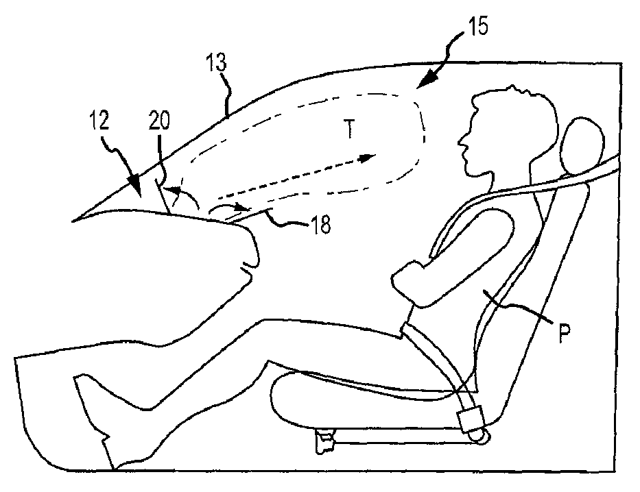
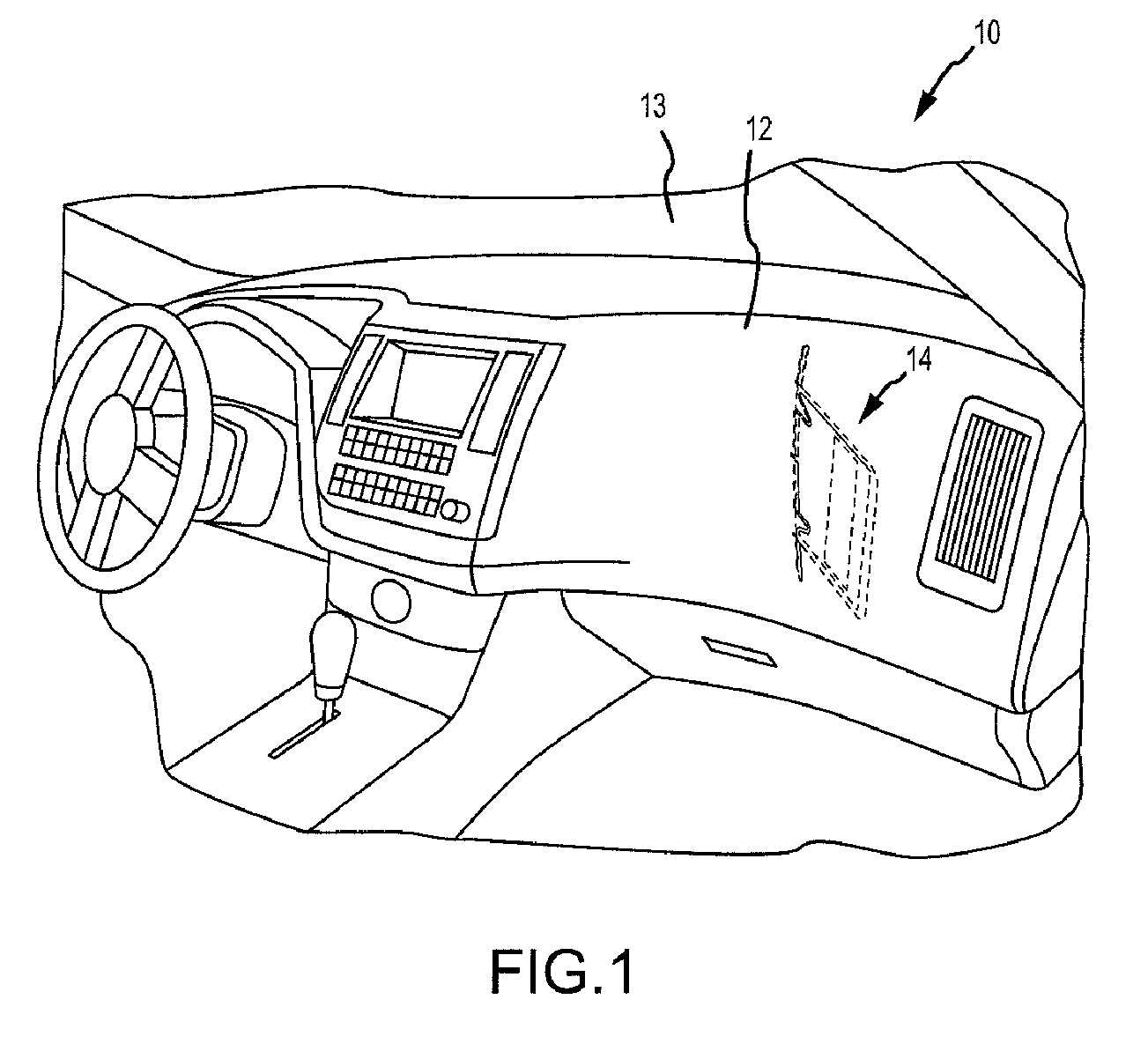
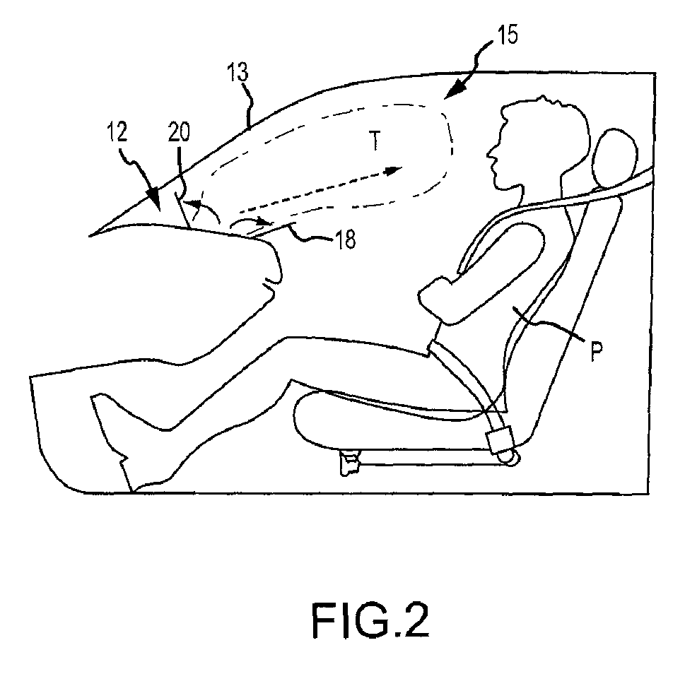
[0024]Referring now to the drawings wherein like reference numerals designate corresponding parts throughout the several views, as discussed above, FIGS. 1-3 are views illustrative of conventional prior art automotive PSIR chute assemblies. In particular, FIG. 3 is a sectional perspective view of a conventional prior art automotive PSIR chute assembly 14. In FIG. 3, chute assembly 14, including chute hinges 22, 24, chute rearward door 28, chute forward door 30, chute sidewalls 32a, 32b, chute end walls 33, connectors 31, and chute flanges 36, 38, are shown to indicate that they are all part of a single injection molded component and that the chute is made of a different material than instrument panel 12 including PSIR rearward door 18 and PSIR forward door 20.

[0025]As discussed above, a conventional PSIR chute assembly including the chute doors, chute hinges, chute walls, and chute flanges is typically made in a single shot injection process of a tough ductile material such as a pol...


PUM


Abstract

An automotive PSIR hidden chute assembly contained behind an automotive instrument panel. The PSIR may include chute forward and rearward doors, first and second chute flanges, and an instrument panel, each constructed of a first hard material, and first and second chute hinges, first and second chute sidewalls and a chute end wall, each constructed of a second tough ductile material, such that the first material and the second material have different thermal expansion properties and different elastic modulus properties.

Description

CROSS-REFERENCE TO RELATED APPLICATION(S)[0001]This application claims the benefit of provisional patent application U.S. Ser. No. 61 / 153,017, filed Feb. 17, 2009, which is expressly incorporated herein by reference.BACKGROUND OF INVENTION[0002]a. Field of Invention[0003]The invention relates generally to automotive instrument panels having automotive Passenger Side Inflatable Restraint (PSIR) components, and more particularly, the invention relates to a two shot automotive PSIR chute.[0004]b. Description of Related Art[0005]Automobiles are commonly equipped with airbags for reducing driver and passenger injuries in the case of an accident. Automobile airbags are generally located in areas where a driver or passenger would potentially contact an automobile interior in the event of an accident. Airbags can reduce injuries by providing a substantially non-solid surface for the driver or passenger to contact, as opposed to the generally solid surfaces of the automotive interior. Althou...

Claims


Application Information

Patent Timeline
Patent Type & Authority Patents(United States)
IPC IPC(8): B60R21/20
CPCB60R21/205B60R21/215B60R2021/21537
Inventor EVANS, GREGG S.GABRIEL, MATTHEW
Owner INOAC USA INC
Why Eureka
Try Eureka