Instrument panel and shield member

a shield and instrument technology, applied in the direction of roofs, pedestrian/occupant safety arrangements, vehicular safety arrangements, etc., can solve the problems of difficult adjustment to cover gaps between respective members, complex assembly process, etc., to prevent gaps, improve the quality of commodities, and improve the appearance

Inactive Publication Date: 2011-06-07
HONDA MOTOR CO LTD
View PDF14 Cites 8 Cited by
  • Summary
  • Abstract
  • Description
  • Claims
  • Application Information

AI Technical Summary

Benefits of technology

[0009]In the instrument panel according to the present invention, the upper portion of the opening is shielded in such a manner that the shield part protruding from the upper edge of the opening of the instrument panel body enters the column cover at a position lower than the upper portion of the column cover. In addition, the lower portion of the opening is shielded in such a manner that the lower portions of the side surfaces of the column cover are inserted into the opening so as to be located on the front side of the shield part in a vehicle longitudinal direction rather than the rear end thereof in a vehicle longitudinal direction. Accordingly, since it is possible to shield a gap between the column cover and the opening of the instrument panel body so as to have a good appearance, it is possible to improve the quality of commodities. Further, since it is not necessary to combine the column cover with the instrument panel body, it is possible to shield a gap between the column cover and the opening of the instrument panel body at a low cost. Furthermore, since the shield part of the instrument panel body enters the column cover at a position lower than the upper portion of the column cover, it is possible to keep an upper space on the front side of the column cover in a vehicle longitudinal direction, and thus to improve a degree of freedom in design for the arrangement of a display, a switch, and the like.
[0011]In this case, since there is provided the side shielding member which shields a gap between the opening of the instrument panel body and the upper portions of the side surfaces of the column cover, it is possible to reliably shield the upper portions of the side surfaces of the column cover by means of the side shielding member.
[0013]In this case, since the protrusion length of the shield part from the opening is set to be larger than the maximum extension length of the steering column, it is possible to maintain the shielding state of the upper portion of the opening even when the steering column is maximally drawn out from the instrument panel body.
[0015]In this case, since the side portions of the column cover move together with the following portion of the shield part even when a distance between the column cover and the opening of the instrument panel body changes due to a shape in accordance with the tilting operation of the column cover, it is possible to efficiently prevent a gap from being formed between the column cover and the opening.
[0019]In the shield member according to the invention, the elastic member includes the upper shield portion which protrudes so as to shield the upper portion of the opening and the side shield portions which are continuously formed with the upper shield portion so as to shield the side portions of the opening. The elastic member is attached to the opening while being sandwiched between the support member and the instrument panel body. Accordingly, it is possible to prevent a gap from being formed in the boundary line between the elastic member and the instrument panel body. As a result, since it is possible to shield a gap between the column cover and the opening of the instrument panel body so as to have a good appearance, it is possible to improve the quality of commodities.

Problems solved by technology

However, in the case where the instrument panel is formed as a member separated from the shield member, an assembling process becomes complex upon attaching the shield member to the instrument panel and the steering column so as to give a good appearance.
In addition, it is difficult to adjust to cover a gap between respective members.

Method used


Image

  • Instrument panel and shield member
  • Instrument panel and shield member
  • Instrument panel and shield member

Examples


Embodiment Construction

[0036]An embodiment of the present invention will be described with reference to the accompanying drawings. In the following description, a longitudinal direction and a transverse direction correspond to a vehicle longitudinal direction and a vehicle transverse direction, respectively.

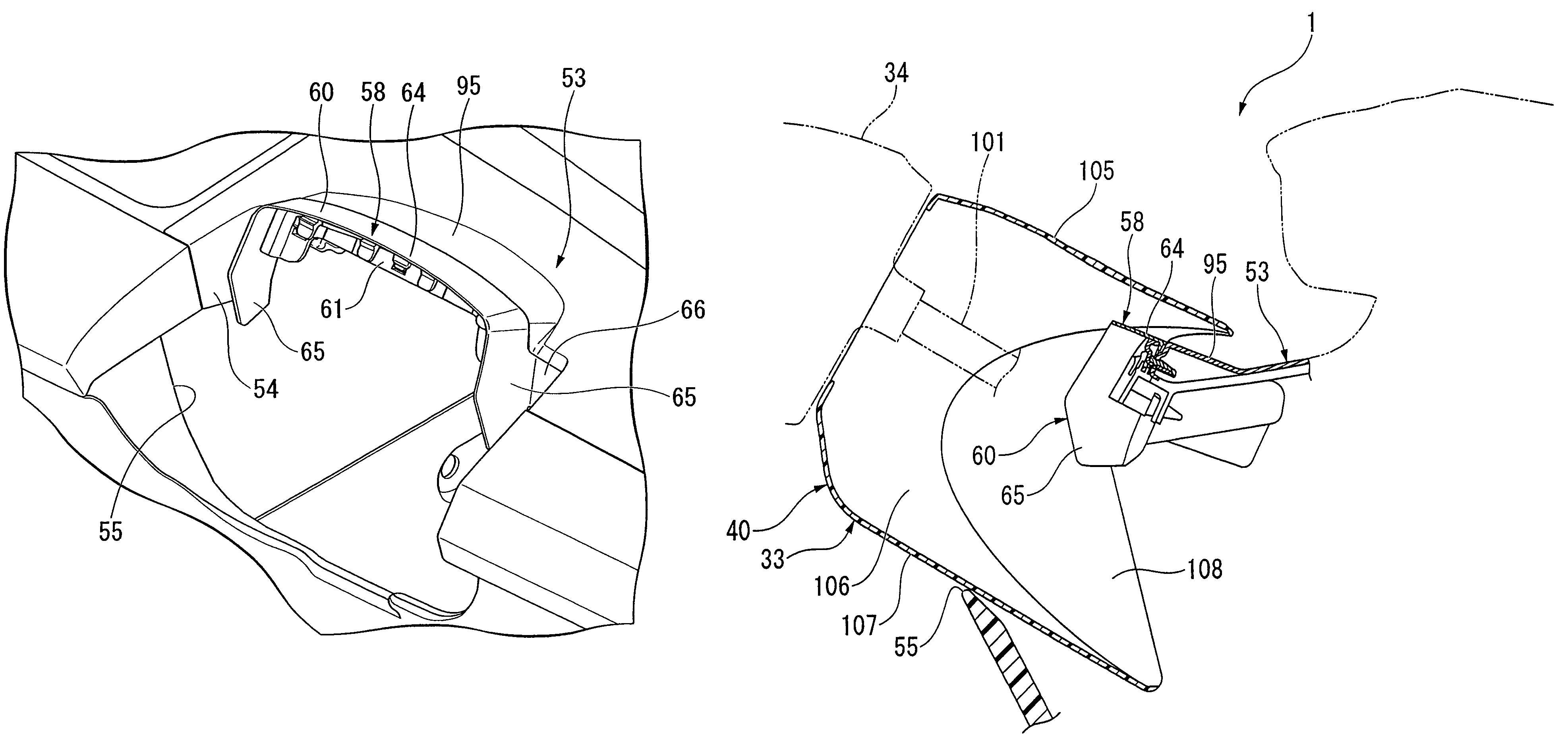
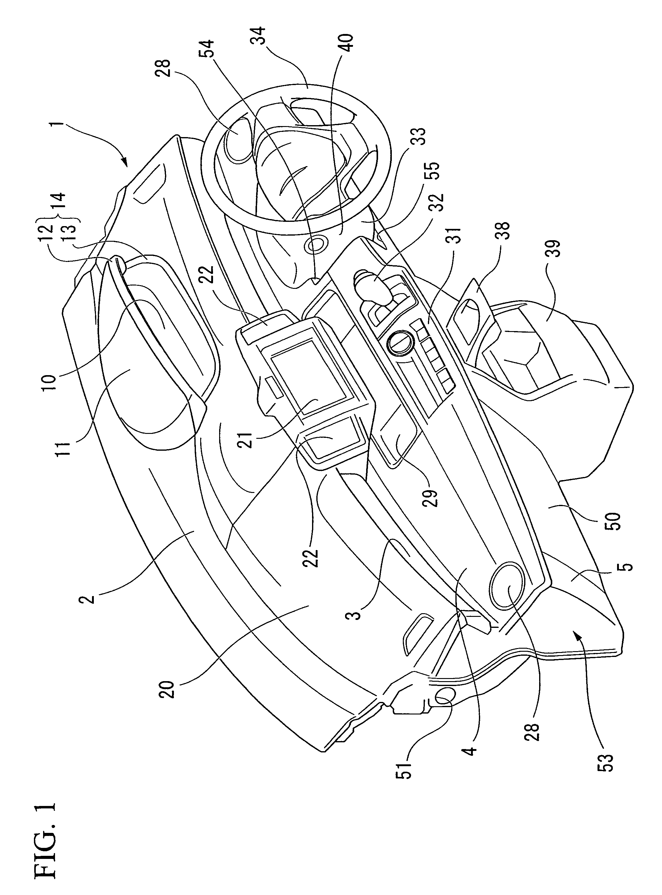
[0037]FIG. 1 is a perspective view showing an instrument panel 1 disposed in the inside of a vehicle room of a vehicle. The instrument panel 1 includes an upper surface part 2; a vertical surface part 3 which extends downward from the rear edge of the upper surface part 2; a stepped upper surface part 4 which extends backward from the lower edge of the vertical surface part 3; and a front surface part 5 which extends downward from the rear edge of the stepped upper surface part 4 so as to be inclined forward.

[0038]The right side part of the upper surface part 2 of the instrument panel 1 is provided with a meter 10 which displays a vehicle speed and the like for a driver; a visor 11 which covers the upp...


PUM


Abstract

An instrument panel is provided with: a steering column having a column cover; and an instrument panel body having an opening into which the steering column is inserted and a shield part which is disposed on an edge of the opening so as to shield a gap between the opening and the column cover, wherein the shield part protrudes from an upper edge of the opening so as to enter the column cover at a position lower than an upper portion of the column cover, and a gap between the column cover and the opening is shielded in such a manner that lower portions of side surfaces of the column cover are inserted into the opening and are disposed on the front side of the shield part in a vehicle longitudinal direction rather than a rear end thereof.

Description

BACKGROUND OF THE INVENTION[0001]Priority is claimed on Japanese Patent Application No. 2008-117809, filed on Apr. 28, 2008, the contents of which are incorporated herein by reference.[0002]1. Field of the Invention[0003]The present invention relates to an instrument panel and a shield member of a vehicle.[0004]2. Description of the Related Art[0005]As an instrument panel of a vehicle, there is known an instrument panel including a movable mechanism such as a tilt mechanism or a telescopic mechanism, where the tilt mechanism allows a steering column to be tilted relative to an instrument panel body and the telescopic mechanism allows the steering column to move in a telescopic manner relative to the instrument panel body. Likewise, in the case where the steering column is configured to be movable relative to the instrument panel body, a gap between the instrument panel body and the steering column changes. For this reason, it is necessary to shield the changing gap. As the related a...

Claims


Application Information

Patent Timeline
Patent Type & Authority Patents(United States)
IPC IPC(8): B60R21/045
CPCB60K35/00B60K37/00B60K2350/941B60K2370/81
Inventor SATO, TADASHI
Owner HONDA MOTOR CO LTD
Why Eureka
Try Eureka