Orthopedic connector system

a technology of orthopedic connectors and connectors, applied in the field of orthopedic connector systems, can solve the problems of long-term loss of wrist function, scar tissue formation, and arthritic degeneration of radiocarpal joints

Inactive Publication Date: 2011-06-07
ACUMED
View PDF91 Cites 165 Cited by
  • Summary
  • Abstract
  • Description
  • Claims
  • Application Information

AI Technical Summary

Benefits of technology

[0004]Chronic scapholunate instability may be treated with a screw, termed a Herbert screw 60. The Herbert screw, when installed, extends across the scapholunate joint and threads into both the scaphoid and lunate bones using spaced threads of the screw. The Herbert screw may fix the scaphoid and lunate bones in position until threaded engagement of the Herbert screw with bone loosens enough over time to permit relative pivotal movement of the scaphoid and lunate bones about the screw's long axis. The Herbert screw thus restricts separation (i.e., relative translational motion) of the scaphoid and lunate bones both before and after pivotal movement of these bones is permitted by this screw.

Problems solved by technology

Injury to the SLIL can lead to arthritic degeneration of the radiocarpal joint and loss of wrist movement.
For example, the Herbert screw may not permit relative bone movement for approximately six weeks after installation, a time period sufficient to result in formation of scar tissue and thus long term loss of wrist function.
In addition, when engagement of the Herbert screw with bone loosens, bone movement generally is restricted substantially to pivotal motion about a single axis defined by the screw.
The scapholunate joint thus cannot achieve its full anatomical range of articulation, and may be even more limited if the Herbert screw is installed at an unsuitable angle.
However, each of these approaches may be unsatisfactory for various reasons.

Method used


Image

  • Orthopedic connector system
  • Orthopedic connector system
  • Orthopedic connector system

Examples


example 1

Exemplary Device for Connecting Bone Members

[0068]This example describes an exemplary connector device 140 for connecting bone members; see FIGS. 5-13.

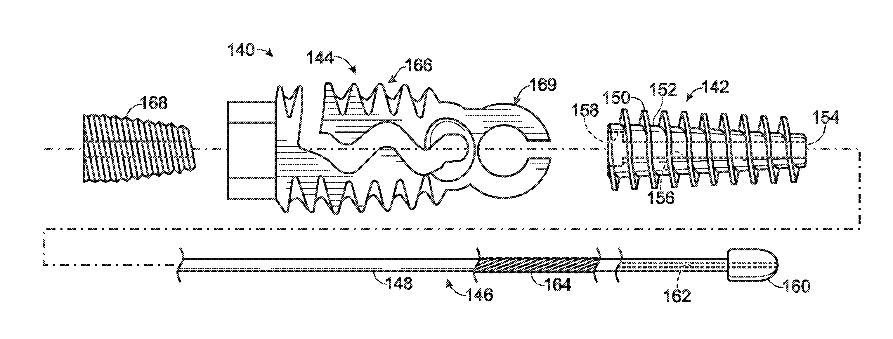
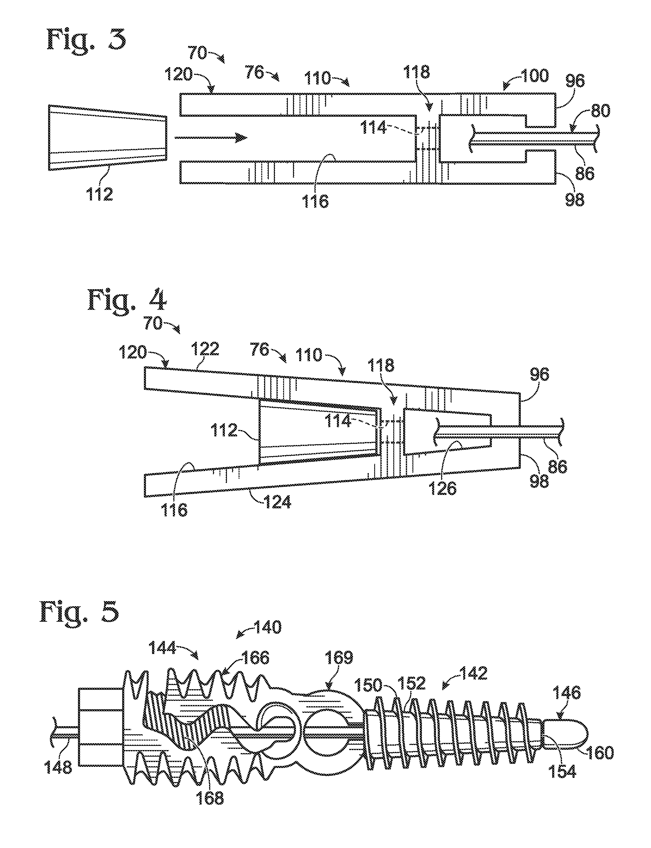
[0069]FIGS. 5 and 6 show connector device 140 in respective assembled and exploded configurations, in the absence of bone. Connector device 140 may include a pair of anchor elements, namely, a leading anchor 142 and a trailing anchor 144. The anchor elements may be coupled to one another via an elongate bridge member 146 that includes a wire 148, also termed a rod, for spanning a junction or gap between the anchor elements. The elongate bridge member may be a discrete, separable component, as shown here, or may be unitary and / or monolithic with leading anchor 142.

[0070]Leading anchor 142 may be structured to be anchored in bone. The leading anchor thus may have an external thread 150 formed on a cylindrical and / or tapered body 152. Here, both external thread 150 and body 152 taper in diameter toward a leading or distal end 154 of the ...

example 2

Exemplary Method of Connecting Bone Members

[0086]This example describes an exemplary method of connecting bone members; see FIGS. 14-20. The method is illustrated using connector device 140 (see Example 1). However, the method may be performed using any suitable connector device such as any of the other connector devices shown and / or described in the present teachings.

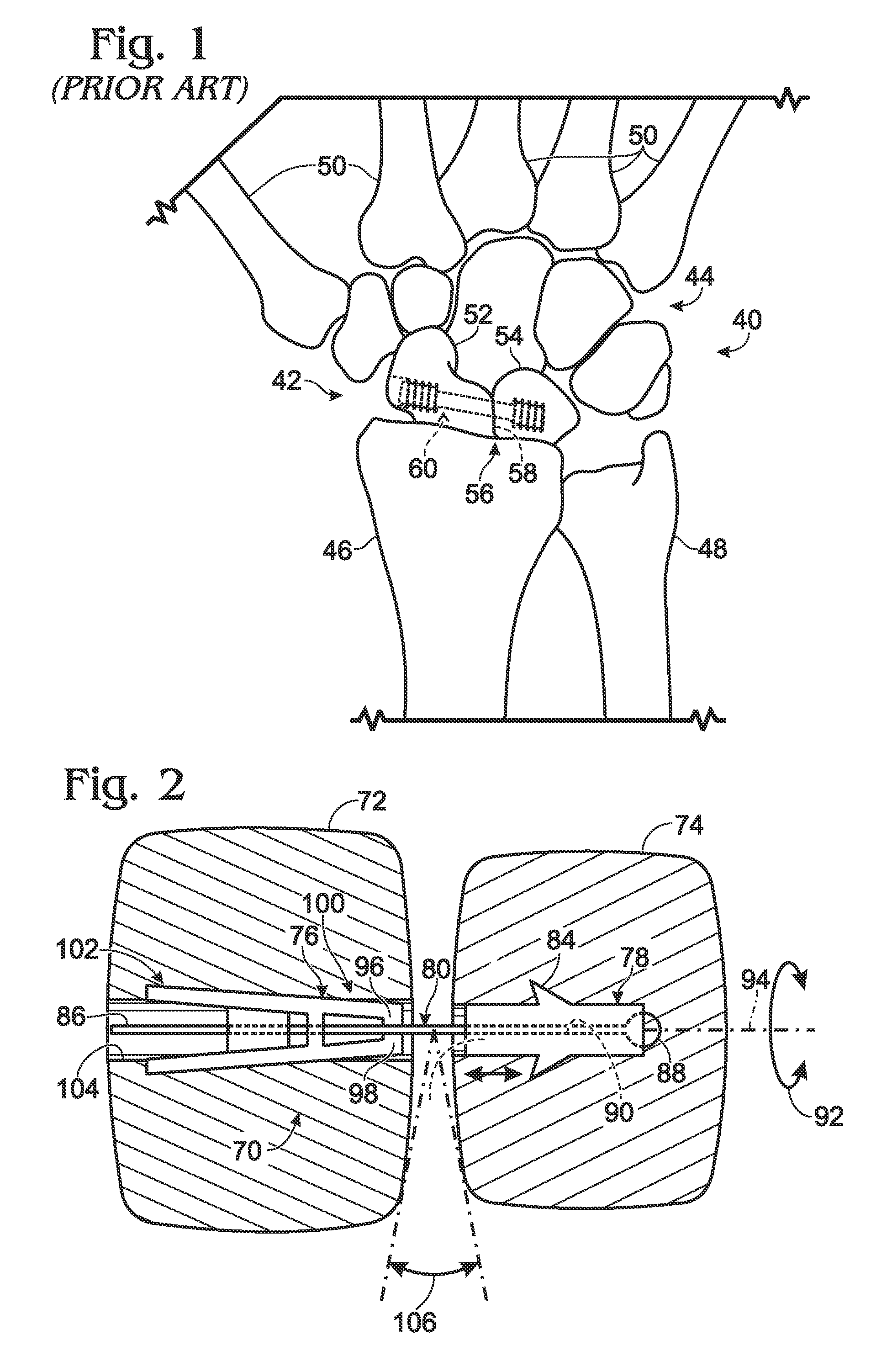
[0087]FIG. 14 shows an exemplary pair of bones, a scaphoid bone 260 and a lunate bone 262, to be connected by performance of an exemplary method of connecting bone members. These carpal bones may be selected for mechanical connection with a connector device due to any suitable indication, such as a fracture and / or a connective tissue injury (e.g., an SLIL injury-see Introduction), among others.

[0088]A path for placement of a connector device may be selected using an elongate guide member 264 (e.g., a guide wire) introduced into and / or through bones 260, 262. The guide wire may be introduced first into the scaphoid bone...


PUM


Abstract

System, including methods, apparatus and components thereof, and kits, for connecting to bone using an anchor element configured to be anchored in bone and having a selectively bendable hinge region. In some embodiments, the system may connect the anchor element to connective tissue, a bridge member, and / or to another anchor element by bending the hinge region while the anchor element is disposed in bone, thereby connecting bone to the connective tissue or bridge member, and / or connecting bone members.

Description

CROSS-REFERENCE TO PRIORITY APPLICATION[0001]This application is based upon and claims the benefit under 35 U.S.C. §119(e) of U.S. Provisional Patent Application Ser. No. 60 / 856,128, filed Nov. 1, 2006, which is incorporated herein by reference in its entirety for all purposes.INTRODUCTION[0002]The skeletal portion of the human wrist, shown in FIG. 1, includes eight carpal bones 40. The carpal bones are disposed in a transverse proximal row 42 and a distal row 44 composed of four bones each. These rows provide a transition between the two bones of the forearm (radius 46 and ulna 48) and the five metacarpals 50 of the hand. The proximal row includes a scaphoid bone 52 and a lunate bone 54, among others. These bones articulate with one another (through a scapholunate joint 56), and also articulate proximally with radius 46 (through a radiocarpal joint), and distally with distal row 44 of the carpal bones.[0003]Trauma to the wrist can produce scapholunate instability by injuring a liga...

Claims


Application Information

Patent Timeline
Patent Type & Authority Patents(United States)
IPC IPC(8): A61F2/08A61B17/04A61F2/42
CPCA61B17/68A61B17/8685A61B17/683
Inventor JENSEN, DAVID G.HORST, STEVEN P.
Owner ACUMED
Why Eureka
Try Eureka