Single-sided lateral-field and phototransistor-based optoelectronic tweezers
a technology of optoelectronic tweezers and lateral fields, applied in the field of single-sided lateral field and phototransistor-based optoelectronic tweezers, to achieve the effect of greater integration flexibility
- Summary
- Abstract
- Description
- Claims
- Application Information
AI Technical Summary
Benefits of technology
Problems solved by technology
Method used
Image
Examples
example 1
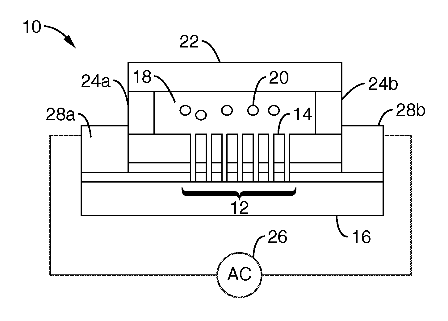
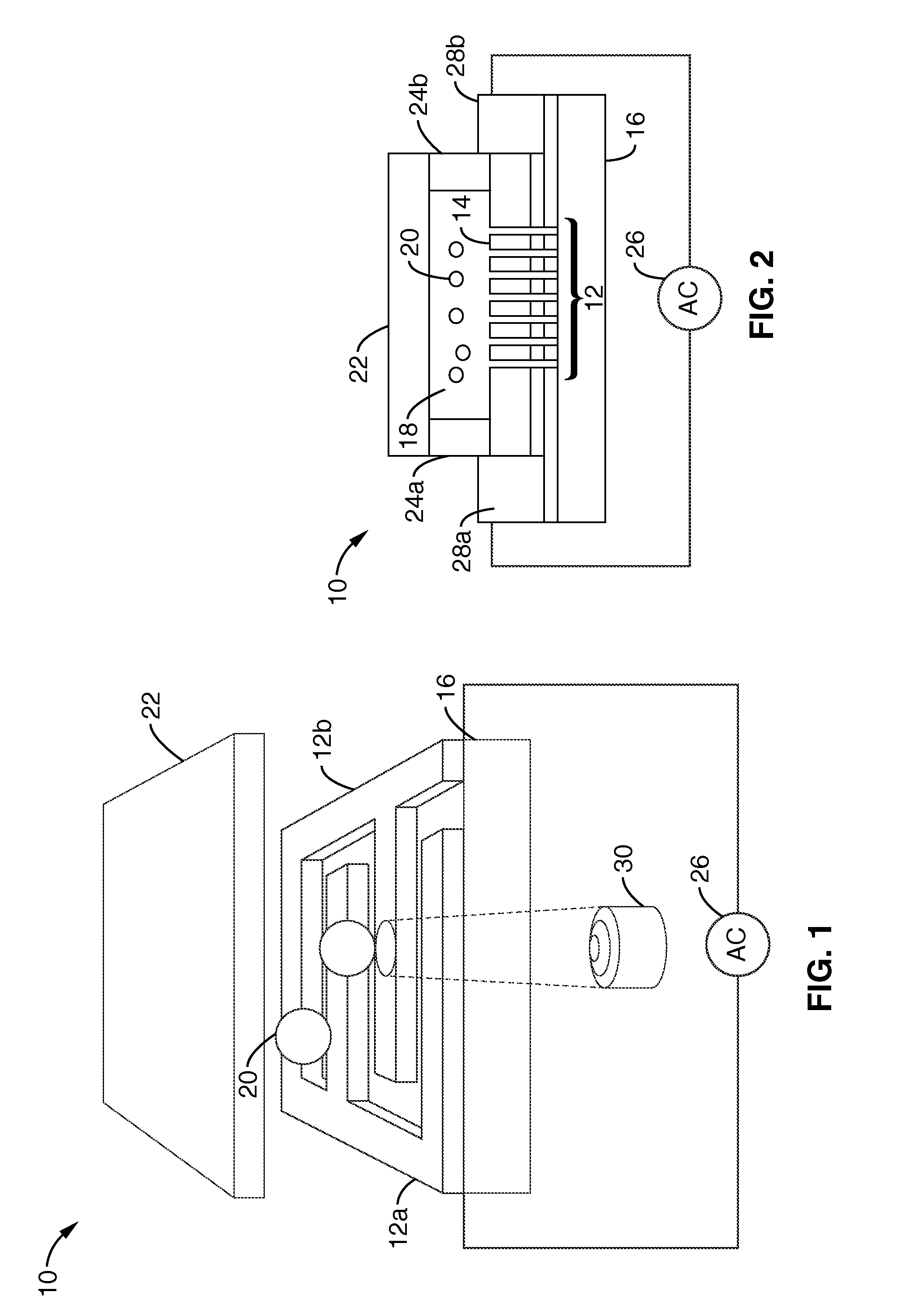
[0055]An interdigitated LOET device as illustrated in FIG. 1 and FIG. 2 was created by depositing 100-nm of ITO on an insulating substrate 16. Other conductive materials may also be used. A 50-nm layer of highly-doped a-Si:H is deposited over the ITO, followed by a 1-μm-thick layer of intrinsic a-Si:H 14. Both a-Si:H layers are deposited by plasma-enhanced chemical vapor deposition. Electrode patterns 12 were etched into the a-Si:H layers by reactive ion etching. The patterns are transferred to the ITO layer by a wet acid etch. Electrical contact pads 28 were created by etching the a-Si:H layers down to the ITO layer, and adding conductive epoxy or another conductive material over the exposed ITO layer.
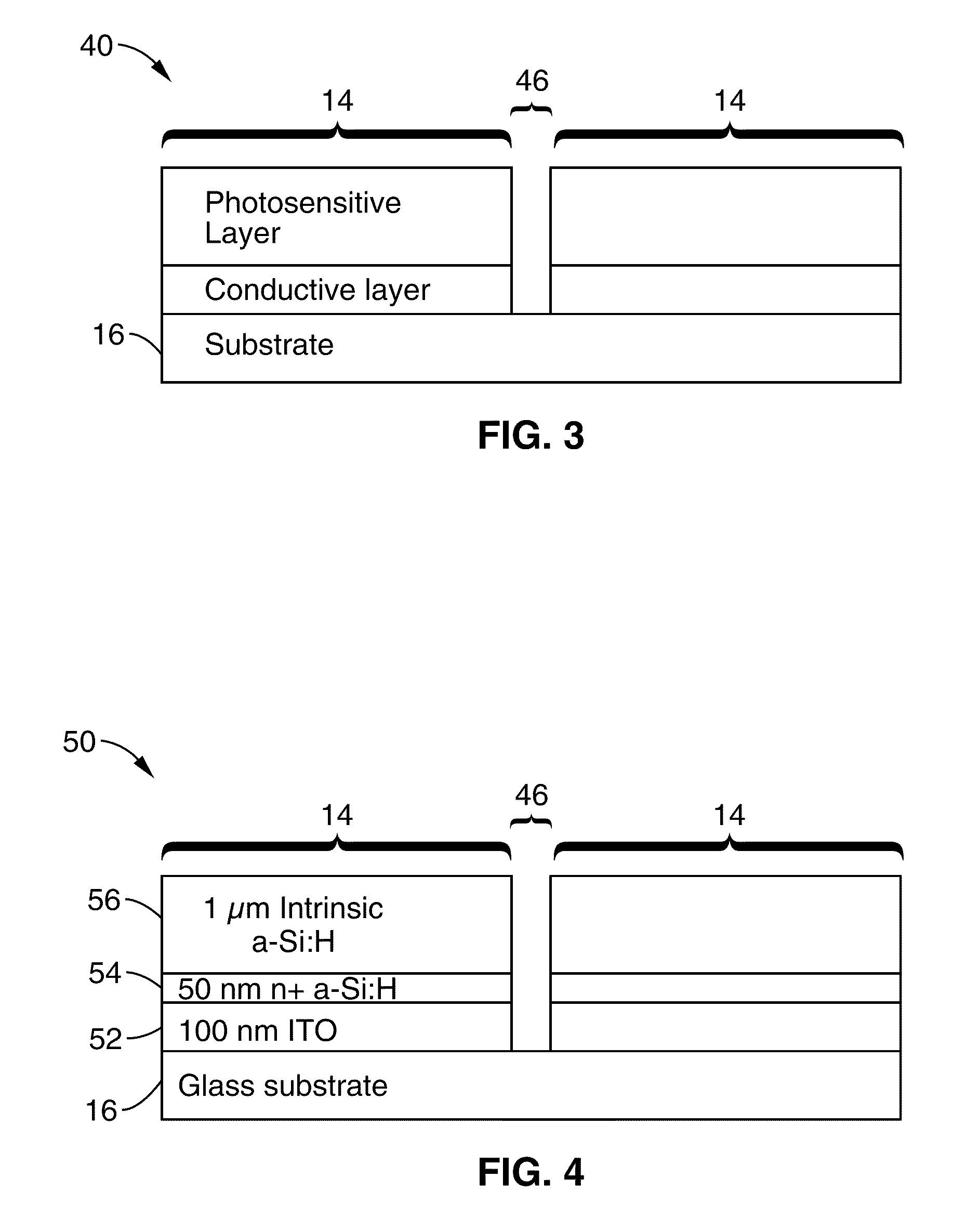
[0056]Referring now to FIG. 3, in a generalized embodiment 40, the device may comprise any type of conductive material 42 on the substrate 16, topped by a photosensitive layer 44 of varying thickness, with individual devices spaced apart by an electrode gap 46.
example 2
[0057]In a specific embodiment 50 shown in FIG. 4, the electrodes 14 comprise a 100-nm-thick indium-tin-oxide (ITO) layer 52 on a glass substrate 16, topped by a 50-nm-thick layer 54 of highly doped hydrogenated amorphous silicon (a-Si:H), and a 1-μm-thick layer 56 of intrinsic a-Si:H. Alternative materials can be used as long as they retain the indicated material properties shown in FIG. 3 (i.e., conductive or photosensitive).
[0058]In one embodiment, the inventive LOET device utilizes 10-μm-wide electrodes, with a 20-μm gap 46 between electrodes. However, other electrode sizes and gaps between the electrodes may be utilized.
[0059]Referring now to FIG. 3, FIG. 5 and FIG. 6, various alternative configurations of the generalized LOET structure can be utilized to improve the electric field characteristics of the LOET device. For example, in the embodiment 60 shown in FIG. 5A, the conductive layer 42 may be undercut. In the embodiment 70 shown in FIG. 5B, the conductive layer 42 is enve...
example 3
[0060]Referring to FIG. 7, illumination of the electrodes in the inventive LOET structure and various embodiments described above causes actuation of OET force, as in a conventional OET device. Significantly, however, as illustrated by FIG. 7, the electric field in the inventive LOET device is parallel to the plane of the electrodes for electrodes that have no undercut of the conductive layer as shown in FIG. 7A, electrodes with an undercut conductive layer as shown in FIG. 7B, electrodes with a conductive layer enveloped by photosensitive layer as shown in FIG. 7C, and electrodes with a thin insulating passivation layer in the gap between the electrodes as shown in FIG. 7D. In FIG. 7A, the high-electric-field regions at the edge of the electrodes are undesirable—the regions above the center of the electrodes are the desired high-electric-field regions. FIG. 7B through FIG. 7D show that the corresponding designs reduce the electric field at the electrode edges.
PUM
| Property | Measurement | Unit |
|---|---|---|
| thick | aaaaa | aaaaa |
| width | aaaaa | aaaaa |
| conductivity | aaaaa | aaaaa |
Abstract
Description
Claims
Application Information
 - R&D
- Intellectual Property
- Life Sciences
- Materials
- Tech Scout
- Unparalleled Data Quality
- Higher Quality Content
- 60% Fewer Hallucinations
Browse by: Latest US Patents, China's latest patents, Technical Efficacy Thesaurus, Application Domain, Technology Topic, Popular Technical Reports.
© 2025 PatSnap. All rights reserved.Legal|Privacy policy|Modern Slavery Act Transparency Statement|Sitemap|About US| Contact US: help@patsnap.com


